MT3170B/71B, MT3270B/71B, MT3370B/71B
Data Sheet
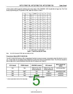
of four pulses will be ignored until the next rising edge of the ESt/DStD. ACK should idle at logic low. The 4-bit
binary representing all 16 standard DTMF digits are shown in Table 1.
FLOW
697
697
697
770
770
770
852
852
852
941
941
941
697
770
852
941
FHIGH
1209
1336
1477
1209
1336
1477
1209
1336
1477
1336
1209
1477
1633
1633
1633
1633
DIGIT
1
b3
0
0
0
0
0
0
0
1
1
1
1
1
1
1
1
0
b2
0
0
0
1
1
1
1
0
0
0
0
1
1
1
1
0
b1
0
1
1
0
0
1
1
0
0
1
1
0
0
1
1
0
b0
1
0
1
0
1
0
1
0
1
0
1
0
1
0
1
0
2
3
4
5
6
7
8
9
0
*
#
A
B
C
D
Tab0le= L1O-GSICerLiOaWl D, 1e=cLoOdGeICBHitIGTHable
Note: b0=LSB of decoded DTMF digit and shifted out first.
Powerdown Mode (MT317xB/337xB)
The MT317xB/337xB devices offer a powerdown function to preserve power consumption when the device is not in
use. A logic high can be applied at the PWDN pin to place the device in powerdown mode. The ACK pin should be
kept at logic low to avoid undefined ESt/DStD and SD outputs (see Table 2).
MT317xB/337xB
ACK (input)
PWDN (input)
ESt/DStD (output)
SD (output)
status
low
low
Refer to Fig. 4 for
timing waveforms
Refer to Fig. 4 for
timing waveforms
normal operation
low
high
high
high+
low
high
low
low
undefined
low
undefined
undefined
powerdown mode
undefined
undefined
Table 2 - Powerdown Mode
+ =enters powerdown mode on the rising edge.
5
Zarlink Semiconductor Inc.

 ZARLINK [ ZARLINK SEMICONDUCTOR INC ]