MT3170B/71B, MT3270B/71B, MT3370B/71B
Data Sheet
Applications
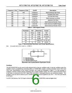
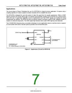
The circuit shown in Figure 3 illustrates the use of a MT327xB in a typical receiver application. It requires only a
coupling capacitor (C1) and a crystal or ceramic resonator (X1) to complete the circuit.
The MT3x70B is designed for user who wishes to tailor the guard time for specific applications. When a DTMF
signal is present, the ESt pin will go high. An external microcontroller monitors ESt in real time for a period of time
set by the user. A guard time algorithm must be implemented such that DTMF signals not meeting the timing
requirements are rejected. The MT3x71B uses an internal counter to provide a preset DTMF validation period. It
requires no external components. The DStD output high indicates that a valid DTMF digit has been detected.
The 4.194304 MHz frequency has a secondary advantage in some applications where a real time clock is required.
A 22-bit counter will count 4,194,304 cycles to provide a one second time base.
VDD
C1
8
1
VDD
DTMF/CP Input
INPUT
MT327xB
7
6
5
2
3
OSC2
OSC1
ESt/DStD
ACK
X1
To microprocessor or
microcontroller
4
VSS
SD
COMPONENTS LIST:
C1 = 0.1 µF ± 10 %
X1 = Crystal or Resonator (4.194304 MHz)
Figure 3 - Application Circuit for MT327xB
7
Zarlink Semiconductor Inc.

 ZARLINK [ ZARLINK SEMICONDUCTOR INC ]