MT312 Initialisation
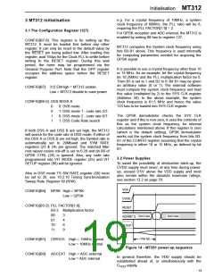
3.3 Initialisation Sequence
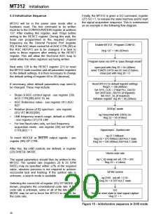
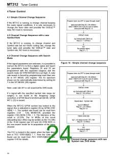
Finally, the MT312 is given a GO command, register
(27) GO =1, to release the state machine and to start
the signal acquisition sequence. This is summarised
as an example in the following flow diagram.
MT312 will be in the power save mode after a
hardware reset. The first command to be written
must be to the CONFIGURATION register at address
127. After loading this register, wait 150µs before
writing to the RESET register. During this wait, the
tuner can programmed to the required channel
frequency via the General Purpose Port (register
20). If the AGC slope control bit of AGC CTRL(39) or
the AGC REF(41) are to be changed, it is best to
write to these registers after writing to the RESET
register. This will allow the front-end AGC loop to
settle while the other registers are being written.
Enable MT312 : Program CONFIG
Reg 127 = 140 (8Chex)
Program tuner via GPP in 'pass through mode'
Next write 128 to the RESET register (21) to reset
the MT312 state machine and all parameter registers
to the default settings. It is then necessary to change
the default setting of register 49 to 50 (decimal).
open port with Reg 20 = 64 (40hex)
send TUNER DATA via I2C bus (5 bytes).
close port with Reg 20 = 0
Reset MT312 to default register settings
Reg21 = 128 (80hex)
Set SYS_CLK = 2*Xtal*PLL_RATIO
Set DISEQQC_RATIO (if required)
Set AGC_SL (if required)
If necessary, other default parameters may need to
be changed. These may include:
•
•
•
•
•
Slope of AGC control signal - see register (39)
ACG CTRL[B0] AGC SL bit
Initialise register: reg 49 = 50 (32hex);
AGC Reference value - see register (41) AGC
REF
DiSEqC mode
Relative phase of IQ spectrum - see register
(25) VIT MODE[B6]
eg Horizontal with 22kHz on:
Reg 22 = 65 (41hex)
LNB frequency search range, default is ±6MHz
- see register (37) FR LIM
For low Baud rates only, set fast frequency
acquisition mode - see register (26) set QPSK
CTRL[B2] = 1
Signal input - Symbol rate
eg 27.5 MBaud:
Reg 23 = 27 (1Bhex) DEFAULT state
Reg 24 = 128 (80hex) DEFAULT state
To invert MOCLK or BKERR output signals - see
register (96) OP CTRL
After this, the LNB controls are defined, in register
(22) DISEQC MODE.
Viterbi code rate
eg V_IQ swap not set, CR = 3/4:
Reg 25 = 4 (4hex)
The signal parameters should then be written to the
MT312. The symbol rate (registers 23 & 25 SYM
RATE) may be specified within ±2% of the required
value, absolute precision is not required to achieve
successful lock and tracking. If the symbol rate is
unknown, a search mode is available.
QPSK control
eg DVB : roll-off = 0.35:
Reg 26 = 0 DEFAULT state
Selecting the correct bit of register (25) VIT MODE, if
known, programs the convolutional code rate. If the
code rate is unknown, some or all of the bits of VIT
MODE may be set to force the MT312 to search for
the code rate.
GO
Release reset state to start signal capture
Reg 27 = 1
Figure 15 - Initialisation sequence in DVB mode
20

 ZARLINK [ ZARLINK SEMICONDUCTOR INC ]