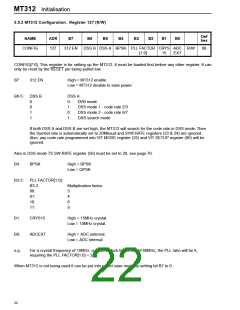
MT312 Software Control
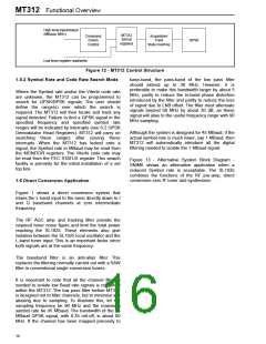
highest register address, because it is only written
once during the initialisation sequence.
2 MT312 Software Control
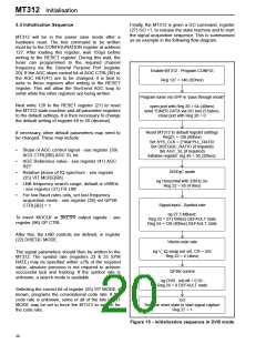
This section describes the sequences of register
operations needed to acquire DVB and DSS
channels with known or unknown parameters.
The CONFIG register can only be reset by the
hardware reset. The MT312 is held in a power saving
mode following the hardware reset.
Communication with the MT312 is via a standard 2-
wire bus and the first byte following the chip address,
in write mode, is the register address (RADD).
After a hardware reset, the MT312 must be taken out
of the power save mode by writing a one to the MSB
of the CONFIG register (see 1.1 Introduction). When
MT312 is not being used it can be put back into the
power save mode by writing a zero to the MSB of
CONFIG.
The register map is organised to group important
Read registers at the lowest addresses, then the
main control Write registers in the next block of
addresses.
The first register to be written must be the
Configuration register, which has been placed at the
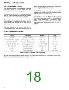
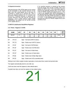
2.1 MT312 Register Map Overview
Address
Description
Section
Type
00 - 06
07 - 19, 108 - 117, 123, 124
20 - 39, 41, 96, 103
40, 42 - 49, 50 - 106, 125
107, 118 - 122
126
Interrupt and Status
Primary signal monitors
Primary control parameters
Secondary parameters
Secondary monitors
Chip identification
5.1to 5.4-
5.5 to 5.17
4 to 4.20
read
read
write / read
write / read
read
11.1.1 to 11.1.52
11.2.1 to 4.22
5.18
read
127
Chip configuration
4.22
write / read
Table 2 - MT312 register map overview
All write / read registers take on default values on full software reset, except for the configuration register (127),
that is only reset to the default value by a hardware reset.
18

 ZARLINK [ ZARLINK SEMICONDUCTOR INC ]