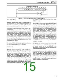
Functional Overview MT312
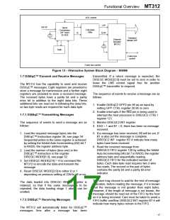
AGC control
I
I I/P
RF I/P
Direct
Conversion
ZIF Tuner
SL1935
Low pass
Filter
Q
Q I/P
Transport
stream O/P
Channel
Decoder
MT312
Tank
2-wire bus
control
2-wire bus control
Figure 13 - Alternative System Block Diagram - SNIM6
1.7 DiSEqC™ Transmit and Receive Messages
transmitted. If a return message is expected, the
DISEQC MODE[2:0] must be set to zero in order to
leave the LNB control signal free for another
DiSEqC™ transmitter to respond.
The MT312 has the capability to send and receive
DiSEqC™ messages. Eight registers are provided to
store a message for transmission and a further eight
registers are provided to store a received message.
The received bytes have a parity bit and a parity
error bit in addition to the eight data bits. These
additional bits are read out in following the data bits,
so two byte reads are required for each data byte.
The sequence of events to receive a message are as
follows:
1. Enable DiSEqC2 GPP2 pin 46 as an input by
setting GPP CTRL register 20 B5 to zero.
2. Enable interrupts if the IRQ pin is being used to
interrupt the host processor in DISEQC2 CTRL1
register 121.
1.7.1 DiSEqC™ Transmitting Messages
3. Monitor DISEQC2 INT register.
The sequence of events to send a message are as
follows:
4. If B3 = 1 and B1 = 0, there has been no message
received.
5. If a message has been received, B0 will be set, If
B1 is also set the message is complete.
DISEQC2 INT register B7-4 indicate how many
bytes have been received.
1. Load the required message bytes into the
DiSEqC™ Instruction register 36, see page 34.
Sequential writes to the same register is achieved
by setting the Inhibit Auto Incrementing (IAI) bit 7
in RADD, the register address byte.
6. Read the received message from
DISEQC2 FIFO register 120 by setting the Inhibit
Auto Incrementing (IAI) bit 7 in RADD, the register
address byte and sequentially reading
DISEQC2 FIFO for the indicated number of
bytes. Each data byte read requires two 2-wire
bus reads. The second or the pair of bytes
contains the parity bit and a parity bit error
indicator.
2. Load the number of bytes (less one) in the
DiSEqC™ instruction in the register
DISEQC MODE[5:3], see page 32.
3. Set DISEQC MODE[2:0] = 4 to command the
MT312 to encode the data and transmit the
message.
4. Reset DISEQC MODE[2:0] to either 0 or 1
depending on previous setting of 22kHz off or on.
The user may choose to wait for the end of message
indication, before reading the message, if it is known
that the message is not greater than eight bytes.
However, if the length of message is not known, the
message should be read out of the FIFO by the host
as it is being received. Care must be taken to avoid a
FIFO buffer overflow. DISEQC2 INT register B7-4 will
indicate how many bytes remain in the FIFO.
The data loaded into DISEQC INSTR register is
retained, so that if the same message is to be
repeated, the data loading stage 1 above can be
omitted.
1.7.2 DiSEqC™ Receiving Messages
The MT312 will automatically listen for DiSEqC™
messages 5ms after
a
message has been
17

 ZARLINK [ ZARLINK SEMICONDUCTOR INC ]