Functional Overview MT312
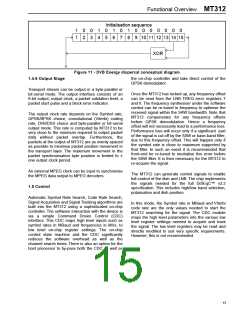
Initialisation sequence
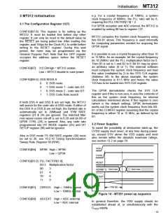
1 0 0 1 0 1 0 1 0 0 0 0 0 0 0
1 2 3 4 5 6 7 8 9 10 11 12 13 14 15
XOR
Figure 11 - DVB Energy dispersal conceptual diagram
1.4.6 Output Stage
the on-chip controller and take direct control of the
QPSK demodulator.
Transport stream can be output in a byte-parallel or
bit-serial mode. The output interface consists of an
8-bit output, output clock, a packet validation level, a
packet start pulse and a block error indicator.
Once the MT312 has locked up, any frequency offset
can be read from the LNB FREQ error registers 7
and 8. The frequency synthesiser under the software
control can be re-tuned in frequency to optimise the
received signal within the SAW bandwidth. Note that
MT312 compensates for any frequency offsets
before QPSK demodulation. Hence a frequency
offset will not necessarily lead to a performance loss.
Performance loss will occur only if a significant part
of the signal is cut off by the SAW or base-band filter,
due to this frequency offset. This will happen only if
the symbol rate is close to maximum supported by
that filter. In such an event it is recommended that
front-end be re-tuned to neutralise this error before
the SAW filter. It is then necessary for the MT312 to
re-acquire the signal.
The output clock rate depends on the Symbol rate,
QPSK/BPSK choice, convolutional (Viterbi) coding
rate, DVB/DSS choice and byte-parallel or bit-serial
output mode. This rate is computed by MT312 to be
very close to the minimum required to output packet
data without packet overlap. Furthermore, the
packets at the output of MT312 are as evenly spaced
as possible to minimise packet position movement in
the transport layer. The maximum movement in the
packet synchronisation byte position is limited to ±
one output clock period.
An external MPEG clock can be input to synchronise
the MPEG data output to MPEG decoders.
The MT312 can generate control signals to enable
full control of the dish and LNB. The chip implements
the signals needed for the full DiSEqC™ v2.2
specification. This includes high/low band selection,
polarisation and dish position.
1.5 Control
Automatic Symbol Rate Search, Code Rate Search,
Signal Acquisition and Signal Tracking algorithms are
built into the MT312 using a sophisticated on-chip
controller. The software interaction with the device is
via a simple Command Driven Control (CDC)
interface. This CDC maps high level inputs such as
symbol rates in MBaud and frequencies in MHz, to
low level on-chip register settings. The on-chip
control state machine and the CDC significantly
reduces the software overhead as well as the
channel search times. There is also an option for the
host processor to by-pass both the CDC as well as
In this mode, the Symbol rate in MBaud and Viterbi
code rate are the only values needed to start the
MT312 searching for the signal. The CDC module
maps the high level parameters into the various low
level register settings needed to acquire and track
the signal. The low level registers may be read and
directly modified to suit very specific requirements.
However, this is not recommended.
15

 ZARLINK [ ZARLINK SEMICONDUCTOR INC ]