MA2910
fields of instruction 53 contain the value 90 so that it will be in
the MA2910 register/counter when the contents of the address
54 are in the pipeline register.
This requires that the instruction at address 53 loads the
register/counter. Now,during the execution of instruction 5 (at
address 54), if the test failed, the contents of the register
(value=90) will select the address of the next microinstruction.
If the test input passes, the pipeline register contents
(value=80) will determine the address of the next
microinstruction. Therefore, this instruction provides the ability
to select one of two subroutines to be executed based on a test
condition.
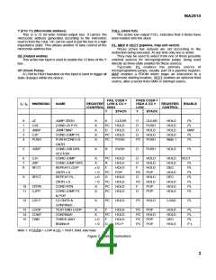
Figure 10: 7 COND JUMP R/PL (JRP)
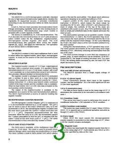
Instruction 6: Conditional Jump Vector.
This instruction provides the capability to take the branch
address from a third source heretofore not discussed. In order
for this instruction to be useful, the MA2910 output VECT is
used to control a three-state control input of a register, buffer,
or PROM containing the next microprogram address. This
instruction provides one technique for performing interrupt
type branching at the microprogram level. Since this
instruction is conditional, a pass causes the next address to be
taken from the vector source, while failure causes the next
address to be taken from the microprogram counter.
In the example, if the Conditional Jump Vector instruction is
contained at location 52, execution will continue at vector
address 20 if the CC input is LOW and the microinstruction at
address 53 will be executed if the CC input is HIGH.
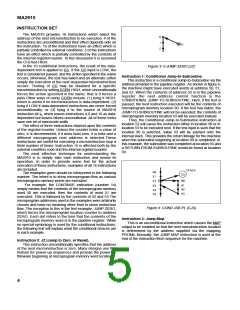
Instruction 8: Repeat Loop, Counter ¹ Zero.
This microinstruction makes use of the decrementing
capability of the register/counter. To be useful, some previous
instruction, such as 4, must have loaded a count value into the
register/counter. This instruction checks to see whether the
register/counter contains a non-zero value. If so, the register/
counter is decremented, and the address of the next
microinstruction is taken from the top of the stack.
If the register/counter contains zero, the loop exit condition
is occurring; control falls through to the next sequential
microinstruction by selecting µPC; the stack is POP’d by
decrementing the stack pointer, but the contents of the top of
the stack are thrown away.
In this example, location 50 is most likely to have contained
a Push/Conditional Load Counter instruction which would
have caused address 51 to be PUSHed on the stack and the
counter to be loaded with the proper value for looping the
desired number of times.
In this example, since the loop test is made at the end of
the instructions to be repeated (microaddress 54), the proper
value to be loaded by the instructions at address 50 is one less
than the desired number of passes through the loop .
This method allows a loop to be executed 1 to 4096 times.
If it desired to execute the loop from 0 to 4095 times, the
firmware should be written to make the loop exit test
immediately after loop entry.
Single-microinstruction loops provide a highly efficient
capability for executing a specific microinstruction a fixed
number of times. Examples include fixed rotates, byte swap,
fixed point multiply, and fixed point divide.
Figure 9: 6 COND JUMP VECTOR (CJV)
Instruction 7: Conditional Jump.
Conditional Jump via the contents of the MA2910 Register/
Counter or the contents of the Pipeline register. This
instruction is very similar to instruction 5; the Conditional
Jump-to-subroutine via R or PL. The major difference between
instruction 5 and instruction 7 is that no push onto the stack is
performed with 7.
The example depicts this instruction as a branch to one of
the two locations depending on the test condition. The
example assumes the pipeline register contains the value 70
when the contents of address 52 are being executed. As the
contents of address 53 are clocked into the pipeline register,
the value 70 is loaded into the register/counter in the MA2910.
The value 80 is available when the contents of the address 53
are in the pipeline register. Thus, control is transferred to either
address 70 or address 80 depending on the test condition.
Figure 11: 8 ERPEAT LOOP, CNTR ¹ 0 (RFCT)
6

 ZARLINK [ ZARLINK SEMICONDUCTOR INC ]