MA2910
OPERATION
The MA2910 is a SOS microprogram controller intended
for use in high speed microprocessor applications. Besides the
capability of sequential access, it provides conditional
branching to any microinstruction within its 4096-microword
range.
A last-in, first-out stack provides microsubroutine return
linkage and looping capability; there are nine nesting levels of
microsubroutines. Microinstruction loop count control is
provided with a count capacity of 4096.
points to the last file word written. This allows stack reference
operations (looping) to be performed without a POP.
Explicit control of the stack pointer occurs during
instruction 0 (RESET), which makes the stack empty by
resetting the SP to zero. After a RESET, and whenever the
stack is empty, the contents of the top of the stack are
undefined until a push occurs. Any POPs performed while the
stack is empty put undefined data on the outputs and leave the
stack at zero.
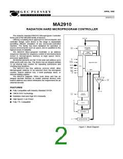
The device is controlled by 16, 4-bit microinstructions. The
PLA decodes the microinstructions on I(3:P) and produces
select control codes for the multiplexer, register/counter,
microprogram counter register, and stack. The 4-bit
microinstructions also generate three active low enable
signals (PL, VECT, and MAP) for external use. The operation
of each device block is detailed below:
The stack pointer operates as an up/down counter. During
microinstructions 1,4, and 5, the PUSH operation may occur.
This causes the stack pointer to increment and the file to be
written with the required return linkage. On the cycle following
the PUSH, the return data is at the new location pointed to by
the stack pointer.
During five microinstructions, a POP operation may occur.
The stack pointer decrements at the next rising clock edge
following a POP, effectively removing old information from the
top of the stack.
The stack pointer linkage is such that any sequence of
pushes, pops, or stack references can be achieved. At RESET
(instruction 0), the depth of nesting becomes zero. For each
PUSH, the nesting depth increases by one; for each POP, the
depth decreases by one.
MULTIPLEXER
The MA2910 contains a four-input multiplexer that is used
to select either the register/counter, direct input, microprogram
counter, or stack as the source of the next microinstruction
address.
REGISTER/COUNTER
The register/counter consists of 12 D-type, edgetriggered
flip-flops, with a common clock enable. It is operated during
microinstructions (8,9,15) as a 12-bit down counter, with result
= zero available as a microinstruction branch test criterion.
This provides efficient iteration of microinstructions.
The register/ counter is arranged such that if it is preloaded
with a number N and is then used as a loop termination
counter, the sequence will be executed exactly N+1 times.
During instruction 15, a three way branch under combined
control of the loop counter and the condition code is available.
When its load control, RLD, is LOW, new data is loaded on the
next positive control transition.
PIN DESCRIPTIONS
VDD and GND (Power and Ground)
The MA2910 operates from a single supply voltage of
5V + 10%
D (0 to 11) (Direct input)
These connections provide direct input to the register/
counter, and the multiplexer. D0 is the least significant bit and
D1 the most significant
I (0 to 3) (instruction bus)
The output of the register/counter is available to the
multiplexer as a source for the next microinstruction address.
The direct input furnishes a source of data for loading the
register /counter.
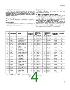
The data on these inputs is read on the rising edge of CP. It
determlnes the instruction to be executed in accordance with
table 1.
CC (Condition Code)
This active low input is used to determine the result of
conditional instructlon. LOW indicates a TRUE conditlon.
MICROPROGRAM COUNTER-REGISTER
The Microprogram Counter Register (µPC) is composed of
a 12-bit incrementer followed by a 12-bit register. The (µPC)
can be used in one of two ways: When the carry-in to the
incrementer is HIGH, the microprogram register is loaded onto
the next clock cycle with the current Y output word plus one
(Y + 1 ➝ µPC). Sequential microinstructions are thus
executed. When the carry-in is LOW, the incrementer passes
the Y output unmodified so that the µPC is reloaded with the
same Y word on the next clock cycle (Y ➝ µPC). The same
microinstruction is thus executed any number of times.
CCEN (Condition code enable)
This active low input enables the CC input. When CCEN is
HIGH, CC is ignored and a conditional operation executed as
though CC were LOW (TRUE).
CI (Carry input)
When HIGH this input causes the microprogramme
counter register to increment on the rising edge of CP. When
LOW the counter remains unchanged.
STACK AND STACK POINTER
RLD (Register load)
The third source available at the multiplexer input is a
9-word by 12-bit stack. The stack is used to provide return
address linkage when executing microsubroutines or loops.
The stack contains a built-in stack pointer (SP) which always
This active low input loads the register/counter from the D
bus on the rising edge of CP. It will override any HOLD or DEC
instruction specified by data on the I bus.
2

 ZARLINK [ ZARLINK SEMICONDUCTOR INC ]