MA17503
3.3.1 Address/Data Bus (AD Bus)
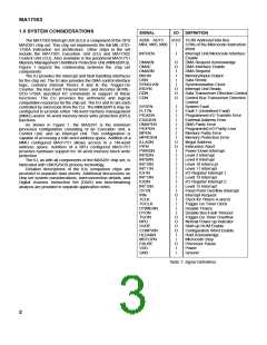
3.0 INTERFACE SIGNALS
Input/Output/Hi-z. These signals comprise the multiplexed
address and data bus. During internal bus operations, the AD
Bus accommodates the transfer of Internal I/O commands and
data from the MA17501 Execution Unit to the lnterrupt Unit. lt
also accommodates the transfer of data from the lnterrupt Unit
to the Execution Unit in response to internal I/O commands.
AD00 is the most significant bit position and AD15 is the least
significant bit position of both the 16-bit data and 16-bit
command. A high on this bus corresponds to a logic 1 and a low
corresponds to a logic 0.
Commands on the AD Bus are passed through transparent
latches during the low state of input/output SYNCLKN cycles
and are latched at the low-to-high transition of SYNCLKN. Data
on the AD Bus, is either clocked into the lU by the high-to-low
transition of SYNCLKN or placed there by the lU during the low
portion of SYNCLKN.
All signals comply with the voltage levels of Table 1. In
addition, each of these functions is provided with Electrostatic
Discharge (ESD) protection diodes. All unused inputs must be
held to their inactive state via a connection to VDD or GND.
Throughout this data sheet, active low signals are denoted
by either a bar over the signal name or by following the name
with an “N’’ suffix (e.g., DMAKN). Referenced signals that are
not found on the MA17503 are preceded by the originating
chip’s functional acronym in parentheses (e.g., (EU)OSC).
Following is a description of each pin function grouped
according to functional interface. The function name is
presented first, followed by its acronym, its type, and its
description. Function type is either input, output, high
impedance (Hi-z), or a combination thereof. Timing
characteristics of each of the functions described is provided in
Section 5.0.
3.3.2 Microcode Bus Bits 4, 5 and 6 (M04, 05 & 06)
Inputs. M04, M05, M06 are bits 4, 5 and 6 of the 20-bit
Microcode Bus and are coded in the 40-bit microcode
instruction as bits 4, 5 and 6. These bits are latched into the IU
at the SYNCLKN high-to-low transition and are decoded for
commanding the Fault Register, the DMA interface, the NPU
discrete, and for providing the 4-bit priority encoded interrupt
vector to the EU. lU microcode command cycles are extended
to six (EU)OSC cycles by INTREN low. Microcode bits 5 and 6
provide control of DDN during memory and external I/O cycles.
The microcode bus is not latched during DMA or the Hold state
(DMAKN or HLDAKN low).
3.1 POWER LNTERFACE
The power interface consists of one 5V VDD connection
and one GND connection.
3.2 CLOCKS
The clock interface, discussed below, provides
synchronization for lnterrupt Unit operations and the clock
inputs for the interval and watchdog timers.
3.2.1 Synchronisation Clock (SYNCLKN)
Input. The MA17501 Execution Unit (EU) generates the
SYNCLKN signal for the Interrupt Unit. The Interrupt Unit uses
this signal to synchronise system inputs (e.g., interrupts and
faults) to the MAS281 machine cycle and to control all other
internal functions.
3.4 BUS CONTROL
The following is a discussion of the signals used to control
the AD Bus and M Bus. They enable the respective busses at
the proper time and control system access to the MAS281
System AD Bus.
3.2.2 Timer Clock (TCLK)
Input. TCLK is a 100 KHz, user provided clock signal that
drives the interval timers A and B, and the Bus Fault timer.
TCLK is synchronised to the MAS281 machine cycle, via
SYNCLKN, before being sent to the interval timers. This allows
the lU to implement the Internal l/O Commands associated with
timer operation.
The synchronised version of TCLK drives interval timer A,
clocking it once every 10 microseconds. The synchronised
TCLK is divided by 10 to provide a 10 KHz clock for driving
interval timer B, clocking it once every 100 microseconds.
The unsynchronised TCLK is used to increment the Bus
Fault watchdog timer. When DSN drops low, the Bus Fault
timer is enabled to count and expires after two TCLK high-to-
low transitions.
3.4.1 Data Strobe (DSN)
Input. The Interrupt Unit receives DSN from the Execution
Unit. The DSN high-to-low transition starts the Bus Fault
watchdog timer and during successful bus data transfers, the
low-to-high transition halts and resets the Bus Fault watchdog
timer. DSN is also instrumental in controlling the DDN signal
during MAS281 Read/lnput bus cycles.
3.4.2 Memory/lnput-Output (M/ION)
Input. The Interrupt Unit receives M/ION from the Execution
Unit. M/ION low enables l/O command decoding logic M/ION
also selects the FT bit to set in response to a low on MPROEN
and EXADEN.
3.4.3 Interrupt Unit Ready (IRDYN)
3.2.3 Trigger-Go Clock (TGCLK)
Output. The Interrupt Unit uses the IRDYN signal to cause
the Execution Unit clock generation state machine to inject one
wait state into lnternal I/O machine cycles, thus causing the
minimum five (EU)OSC period machine cycle to be extended to
a six (EU)OSC period 50% duty cycle machine cycle. Internal
l/O machine cycles occur during execution of the lU
implemented l/O commands listed in Table 2.
Input. This user provided clock drives the autonomous on-
chip system watchdog timer. The Trigger-Go timer is
incremented by the high-to-low transition of TGCLK.
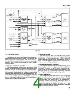
3.3 BUSES
Following is a discussion of the two communication buses
connecting the lnterrupt Unit to the rest of the three chip set.
The AD Bus transfers 16-bit data and commands, while the M
Bus communicates microcode control data.
6

 ZARLINK [ ZARLINK SEMICONDUCTOR INC ]