MA17503
Anti-repeat logic between the FT and Pl prevents latching
more than a single interrupt into the Pl before the user interrupt
service routine has cleared the FT. The microcoded interrupt
service routine reads the interrupt priority vector from the
Interrupt Unit and clears the serviced interrupt from the Pl. At
this point the Pl is ready to latch another interrupt into this bit.
When this microcoded service routine acts on a level 1
interrupt, it clears the Pl bit 1, but the FT maintains the
interrupting fault bit(s). Therefore, a level 1 interrupt would be
latched again if there were no anti-repeat logic to prevent a
never ending loop of interrupts from occurring.
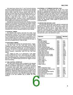
2.8 INTERNAL I/O COMMAND DECODE LOGIC
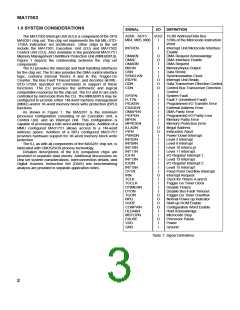
The Interrupt Unit implements the 26 MIL-STD-1750A
specified l/O command functions listed in Table 2. The lU also
decodes an additional 386 commands that are implemented in
the MMU(BPU) and the two Status Word XlO commands that
are handled in microcode for AD Bus control. The lU continually
monitors AD Bus traffic. When M/lON is low, the lU latches the
information present on the AD Bus during the address portion
of the bus cycle. This information is subsequently decoded and
creates the appropriate control signals to perform the l/O
command function.
Interrupts are serviced at the end of the currently executing
instruction if not masked and if interrupts are enabled. System
software servicing level 1 interrupts must clear the FT via the
RCFR internal l/O command at some point in the routine to
allow subsequent faults to latch a level 1 interrupt request. A
non-destructive read of the FT is provided by the internal I/O
command RFR, but this command should be used carefully.
2.9 MICROCODE DECODE LOGIC
The microcode decode logic can be split into command and
control functions. Microcode instruction bits 4, 5 and 6 are
decoded as commands for the FT, the interrupt interface, the
DMA interface, and the discrete output signal, NPU. The
microcode command interface is enabled when lNTREN is
pulled low and is disabled during DMA and the Hold state.
Microcode bits 5 and 6 provide control of DDN during memory
read and write cycles, and external l/O cycles.
2.5 INTERVAL TIMERS
The Interrupt Unit contains both MIL-STD-1750A 16-bit
interval timers, A and B. The TCLK input is synchronized with
SYNCLKN and increments Timer A once a TCLK period. Timer
B is incremented by the synchronized TCLK divided by 10.
Timer A overflow sets Pl bit 7 and Timer B overflow sets Pl bit 9.
The timers are controlled via the l/O command decode logic, or
they can be disabled via the DTlMERN input.
Operation
Command Mnemonic
Code (Hex)
Output
Set Fault Register
Set Interrupt Mask
Clear Interrupt Request
Enable Interrupts
0401
2000
2001
2002
2003
2004
2005
200A
200E
4004
4005
4006
4007
4008
4009
400A
400B
400C
400D
400E
SFR
SMK
CLIR
ENBL
DSBL
RPI
2.6 WATCHDOG TIMERS
The Interrupt Unit contains two watchdog timers, Trigger-
Go and Bus Fault. The Bus Fault timer assures timely
completion of all AD Bus cycles by terminating bus cycles over
two TCLK (maximum, minimum one TCLK period) periods in
duration. This function is automatic, but can be disabled by
DTON low. FT bit 5 or 8 is set for terminated l/O transfers or
memory transfers, respectively, when the Bus Fault timer
expires.
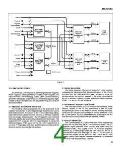
The Trigger-Go timer is an autonomous 16-bit ripple
counter incremented by TGCLK. Upon power-up, the Trigger-
Go timer begins to count. The GO l/O command resets the
timer, thus preventing it from overflowing and causing TGON to
drop low. The DTIMERN input prevents the Trigger-Go timer
from incrementing.
Dlsable Interrupts
Reset Pending Interrupt
Set Pending Interrupt Reglster
Reset Normal Power Up Discrete
Write Status Word
Enable Start Up ROM
Disable Start up ROM
Direct Memory Access Enable
Direct Memory Access Disable
Timer A Start
Timer A Halt
Output Timer A
Reset Tngger-Go
Timer B Start
SPI
RNS
WSW
ESUR
DSUR
DMAE
DMAD
TAS
TAH
OTA
GO
TBS
TBH
OTB
2.7 DMA CONTROL INTERFACE
Timer B Halt
Output Timer B
The DMA control interface logic is contained in the Interrupt
Unit. The interface is composed of the three signals: DMAE,
DMARN, and DMAKN. If the interface is enabled, an internal
l/O command raises DMAE high to indicate the MAS281’s
readiness to accept DMA transfer requests (DMARN low). A
subsequent low on DMARN causes the lU to respond with
DMAKN low. DMAKN low halts the processor and places all AD
Bus and bus control lines in the high-impedance state. Control
is returned to the MAS281 when DMARN is pulled high again.
DTIMERN is the user available way to disable the DMA
interface.
Input
Read Configuration Word
Read Fault Register Wlthout Clear
Read Interrupt Mask
Read Pending Interrupt Reglster
Read Status Word
Read and Clear Fault Reylster
Input Timer A
Input Tlmer B
8400
8401
A000
A004
A00E
A00F
C00A
C00E
RCW
RFR
RMK
RPIR
RSW
RCFR
ITA
ITB
5

 ZARLINK [ ZARLINK SEMICONDUCTOR INC ]