MA17503
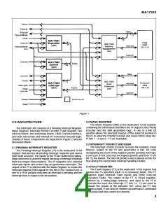
Figure 1
2.2 MASK REGISTER
The Mask Register (MK) is the dedicated 16-bit register
2.0 ARCHITECTURE
containing the information that filters the Pl output to the Priority
Encoder and the IRN generation logic. A one in a MK bit
position allows the interrupt request, of the same bit position in
the Pl, to enter the Priority Encoder and cause IRN to drop low.
Pl bits 1 - 4 and 6 - 15 are maskable.
The Interrupt Unit consists of a Pending Interrupt Register,
Mask Register, Interrupt Priority Encoder, Fault Register, two
interval timers, two watchdog timers, DMA Control interface,
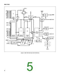
and both microcode and internal I/O instruction decode logic.
Details of these components are depicted in Figure 2 and are
discussed below:
2.3 INTERRUPT PRIORITY ENCODER
The Interrupt Priority Encoder accepts the enabled, mask
filtered, output of the Pl and generates a four bit code
designating the level of the highest priority pending interrupt.
Level zero (Pl bit zero) has the highest priority and level 15 (Pl
bit 15) the lowest. The four bit priority code is placed on the AD
Bus during the microcoded interrupt handling routine.
2.1 PENDING INTERRUPT REGISTER
The Pending Interrupt Register (Pl) is the dedicated 16-bit
register that latches all pending interrupt requests and stores
them until serviced. The inputs to the Pl are buffered by falling-
edge detectors to prevent repeat latching of interrupt requests
held low longer than required. The Pl supports nine external
interrupts inputs and seven chip set generated interrupts. The
output of the Pl is ANDed with the Mask Register to create the
interrupt request (IRN) signal for the MA17502 Control Unit. A
one in a Pl bit position indicates an interrupt is pending and the
interrupt level is equal to the bit position.
2.4 FAULT REGISTER
The Fault Register (FT) is the dedicated 16-bit register that
latches the 15 specified (fault 12 is reserved) faults. The FT
supports eight external Fault inputs and three chip-set
generated Faults. The output of the FT is ORed together,
buffered by a falling-edge detector, and input to the Pl to
generate the level one interrupt. FT bits 13 - 15 are used to
indicate the results of the MAS281 BlT. Once the FT has
latched a fault, it can only be cleared via internal l/O command
(individual fault bits cannot be cleared).
3

 ZARLINK [ ZARLINK SEMICONDUCTOR INC ]