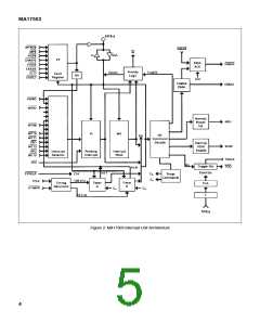
MA17503
3.6.4 DMA Parity Error (DMAPEN)
PIFN causes the MA17501 Execution Unit to hold DSN and
(EU)AS in their inactive state during the transition from error
indication to the beginning of the interrupt servicing routine.
Input. A low on this input indicates a parity error has been
detected during a DMA data transfer. This fault is latched into
FT bit 4.
3.7 DMA INTERFACE
3.6.5 External Address Error (EXADEN)
The DMA lnterface consists of the necessary handshake
signals required to effect transfer of control from the MAS281 to
a DMA controller and back again.
Input. A low on this input indicates execution of an
unimplemented or reserved l/O command has been attempted
(M/lON low) and sets FT bit 5, or an attempt has been made to
access an unimplemented memory address (M/lON high) and
sets FT bit 8.
3.7.1 DMA Transfer Enable (DMAE)
Output. When this output is raised high via execution of the
lnternal I/O command DMAE, direct memory access requests
will be acknowledged by the MAS281. lf DMAE is low, direct
memory access requests will not be acknowledged by the
MAS281.
Provision for detection of these conditions has been made
on the MA17503 in the form of a Bus Fault watchdog timer. If
during an l/O or memory access cycle the system machine
cycle completion circuitry or (EU)RDYN generation logic fails to
provide the (EU)RDYN signal within the required amount of
time, the Bus Fault watchdog timer will terminate the cycle by
forcing IRDYN low and set the appropriate FT bit (FT5 if l/O,
FT8 if memory). The minimum Bus Fault watchdog timeout
period is one TCLK period, the maximum is two TCLK periods.
Setting FT bits 5 or 8 causes PIFN to drop low. This aborts
the MIL-5TD-1750A instruction during which the error occurred
and branches execution to the machine error, level 1, interrupt
service routine, if the interrupt is not masked. lf the interrupt is
masked, execution continues with the next instruction.
FT bit 5 and 8 are not latched during DMA or the Hold state
(DMAKN or HLDAKN low).
3.7.2 DMA Transfer Request (DMARN)
Input. A DMA controller pulls this input low to request
control of the AD Bus and bus control signals for DMA
transfers. DMARN is held low by the DMA controller for the
duration of the DMA transfer, and the low-to-high transition
indicates the DMA controller is finished using the AD Bus.
3.7.3 DMA Transfer Request Acknowledge (DMAKN)
Output. The lnterrupt Unit responds to a low on DMARN, if
DMAE is high, by dropping DMAKN low at the SYNCLKN high-
to-low transition.
3.6.6 Programmed l/O Transmission Error (PIOXEN)
Input. A low on this input indicates a user defined error has
occurred during an l/O transfer. This fault is latched into FT bit
6.
3.8 INTER-CHIP CONTROL
The Inter-Chip Control signals are used to halt the
processor (the three-chip set) during the DMA and HOLD
cycles and during microcode testing.
3.6.7 Fault #7 (FLT7N)
3.8.1 Processor Pause (PAUSEN)
lnput. This is a user definable (spare) fault input. A low on
this input sets FT bit 7.
Output. This output is low during DMA operations (DMAKN
low). PAUSEN is used by the lnterrupt Unit to reset and disable
the Bus Fault Timeout circuitry. PAUSEN is also used by the
MA17501 Execution Unit clock generation circuitry to produce
an internal disable signal. This internal disable signal holds
CLKPCN and SYSCLK1N low and CLK02N high, which halts
processing, and places the DSN, AS, IN/OPN, RD/WN, and
M/ION output buffers, and the AD bus l/O buffers in the high
impedance state, and drop DDN and CDN low to allow DMA
controller access to the MMU(BPU) in shared MMU(BPU)
systems.
3.6.8 System Fault (SYSFN)
Input. A low on this input indicates a system Built-ln Test
error has occurred. This fault is latched into FT bits 13 and 15.
3.6.9 Illegal Address (ILLADN)
FT bits 5 and 8 are set by a low on the EXADEN input or by
the Bus Fault watchdog timer overflow. FT bits 5 and 8 are not
latched, and ILLADN is held high during DMA or the Hold state
(DMAKN or HLDAKN low).
3.8.2 Hold Acknowledge (HLDAKN)
3.6.10 Instruction Abort (PIFN)
Input. HLDAKN resets and disables the Bus Fault Timeout
circuitry, causes DDN and CDN to be brought low, and
prevents latching of microcode commands and decoding. The
Execution Unit responds to a Hold state request (execution of
BPT, or a low on HOLDN) by pulling HLDAKN low.
Output. A low on this output effects a MlL-STD-1750A
instruction abort. When a SYNCLKN high-to-low transition
latches FT bit 0, 5, or 8, the following SYNCLKN high-to-low
transition causes PIFN to drop low and remain low for one
SYNCLKN period (except during DMA and the Hold state, i.e.,
DMAKN or HLDAKN low).
3.8.3 Microcode Stop (MSTOPN)
PIFN directs the MA17502 Control Unit to branch
microcode execution to the interrupt vectoring routine for level
1 interrupt servicing. lf the level 1 interrupt is masked, execution
will resume with the next MIL-STD1750A instruction.
Input. MSTOPN allows microcode to be single-stepped
during testing by GEC Plessey Semiconductors and should be
pulled up to VDD in customer applications.
8

 ZARLINK [ ZARLINK SEMICONDUCTOR INC ]