L9216B/H
Preliminary Data Sheet
September 2001
High-Voltage Ringing SLIC with Ground Start
5 V VCC Operation
Supervision (continued)
Power Ring (continued)
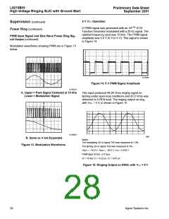
A PWM signal was generated with an HP™ 8116
Function Generator modulated with a 20 Hz signal. The
optimal frequency used was 10 kHz. The PWM signal
amplitude was 5.0 V (0 V to 5 V). This signal is shown
in Figure 14.
PWM Input Signal and Sine Wave Power Ring Sig-
nal Output (continued)
Modulation waveforms showing PWM are in Figure 13
below.
12-3575F
Figure 14. 5 V PWM Signal Amplitude
12-3381(F)
A. Upper = Pwm Signal Centered at 10 kHz
Lower = Modulation Signal
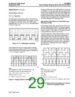
This input produced 44.96 Vrms ringing signal on
tip/ring under open-loop conditions and 42.0 Vrms was
delivered to 5 REN load. The ringing output on ring,
with VCC = 5 V, is shown in Figure 15.
12-3380(F)
1660
B. Same as A but Expanded
Notes:
The modulating 20 Hz signal THD was measured at 1.3%.
Figure 13. Modulation Waveforms
The tip/ring 20 Hz signal THD was measured at 1%.
VBAT1 = –70.6 V, VBAT2 = –26.5 V, VCC = 5.019 V.
PWM input 10 kHz, 5.0 Vp-p.
R1 = 10 kΩ, C1 = 0.22 µF, C2 = 0.47 µF.
Figure 15. Ringing Output on RING, with VCC = 5 V
28
Agere Systems Inc.

 ZARLINK [ ZARLINK SEMICONDUCTOR INC ]