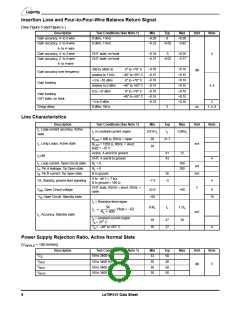
Insertion Loss and Four-to-Four-Wire Balance Return Signal
(See Figure 5 and Figure 6.)
Description
Gain accuracy, 4- to 2-wire
Gain accuracy, 2- to 4-wire
4- to 4- wire
Test Conditions (See Note 1)
0 dBm, 1 kHz
0 dBm, 1 kHz
Min
–0.20
–6.22
Typ
0
–6.02
Max
+0.20
–5.82
Unit
Note
Gain accuracy, 4- to 2-wire
Gain accuracy, 2- to 4-wire
4- to 4-wire
OHT state, on hook
OHT state, on hook
–0.35
–6.37
0
+0.35
–5.77
3
–6.02
–0.10
–0.15
–0.10
–0.15
–0.10
–0.15
–0.35
+0.10
+0.15
+0.10
+0.15
+0.10
+0.15
+0.35
300 to 3400 Hz
relative to 1 kHz
+3 to –55 dBm
relative to 0 dBm
0 to –37 dBm
0° to +70° C
–40° to +85° C
0° to +70° C
–40° to +85° C
0° to +70° C
dB
Gain accuracy over frequency
Gain tracking
3, 4
Gain tracking
OHT state, on hook
–40° to +85° C
+3 to 0 dBm
0 dBm, 1kHz
3
Group delay
3
µs
1, 4, 6
Line Characteristics
Description
Test Conditions (See Note 1)
I in constant-current region
Min
Typ
Max
Unit
Note
I , Loop-current accuracy, Active
L
0.915 I
I
1.085I
L
L
L
L
state
R
R
= 600 Ω, RSGL = open
= 1250 Ω, RSGL = short,
20
20
21.7
LDC
LDC
I , Long Loops, Active state
mA
L
Bat2 = −35 V
Active, A and B to ground
OHT, A and B to ground
61
43
72
I LIM
L
4
4
I , Loop current, Open Circuit state
R = 0
100
200
L
L
µA
I , Pin A leakage, Tip Open state
R = 0
A
L
I , Pin B current, Tip Open state
B to ground
A to −48 V = 7 kΩ,
B to ground = 100 Ω
26
mA
B
VA, Standby, ground-start signaling
−7.5
−5
OHT state, RSGH = short, RSGL =
open
V
V
, Open Circuit voltage
42.8
+60
8
AB
V , Open Circuit, Standby state
−60
10
B
I = Resistive feed region
L
54
0.8I
I
1.2I
L
L
L
-----------------------
IL
=
, Vbat < –62
RL + 400
mA
I , Accuracy, Standby state
L
I = constant-current region
A
L
18
16
27
27
39
T = 25° C
T = –40° to +85° C
4
A
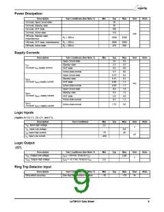
Power Supply Rejection Ratio, Active Normal State
(VRIPPLE = 100 mVrms)
Description
Test Conditions (See Note 1)
50 to 3400 Hz
Min
33
Typ
50
Max
Unit
Note
V
V
V
V
CC
50 to 3400 Hz
50 to 3400 Hz
50 to 3400 Hz
30
40
NEG
BAT1
BAT2
dB
5
30
30
50
50
8
Le79R101 Data Sheet

 ZARLINK [ ZARLINK SEMICONDUCTOR INC ]