Electrical Ranges
V
4.75 to 5.25 V
–4.75 V to V
CC
V
V
V
NEG
BAT1
BAT2
BAT2
–15 to –99 V
–15 V to V
BAT1
AGND/DGND
0 V
BGND with respect to AGND/DGND
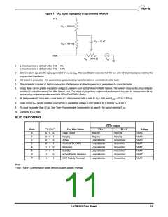
Load resistance on VTX to ground
–100 to +100 mV
20 kΩ minimum
R
0 to V /2
CC
REF
V
R
± 1 V pk
REF
RING
SPECIFICATIONS
Transmission Performance
Description
Test Conditions (See Note 1)
200 Hz to 3.4 kHz (See Figure 9.)
Min
26
Typ
Max
Unit
dB
Ω
Note
1, 4, 6
4
2-wire return loss
Z
, analog output impedance
, analog output offset voltage
, analog input impedance
3
20
+35
+40
20
VTX
0° to +70° C
–40° to +85° C
–35
–40
V
Z
mV
VTX
1
Ω
RSN
Overload level, 2-wire and 4-wire, off
hook
Overload level, 2-wire
Active state
On hook, R
2.5
Vpk
Vrms
2a
2b
= 600 Ω, OHT state
0.88
LAC
THD (Total Harmonic Distortion)
THD, on hook, OHT state
+3 dBm
0dBm, R
–64
–50
–40
dB
5
= 600 Ω
LAC
Longitudinal Performance
(See Figure 7.)
Description
Test Conditions (See Note 1)
Min
Typ
Max
Unit
Note
200 Hz to 1 kHz
normal polarity
reverse polarity
–1, –3*
–2, –4
–2
52
63
54
normal polarity,
–40° to +85° C
1 kHz to 3.4 kHz
normal polarity
reverse polarity
58
4
–2, –4
–1, –3*
–2, –4
–2
Longitudinal to metallic
L-T, L-4 balance
52
58
54
dB
normal polarity,
–40° to +85° C
200 Hz to 800 Hz normal polarity
Active or OHT state
54
4
4
–2, –4
Longitudinal signal generation 4-L
Longitudinal current per pin (A or B)
42
8.5
17
25
mArms
Longitudinal impedance at A or B
0 to 100 Hz, T = +25° C
Ω/pin
A
Idle Channel Noise
Description
Test Conditions (See Note 1)
0° to +70° C
Min
Typ
+7
Max
+11
Unit
Note
C-message weighted noise
dBrnC
–40° to +85° C
+12
–79
–78
–83
4
0° to +70° C
–40° to +85° C
Phosphometric weighted noise
dBmp
Le79R101 Data Sheet
7

 ZARLINK [ ZARLINK SEMICONDUCTOR INC ]