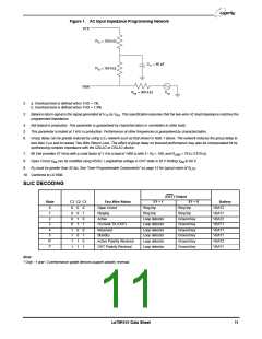
USER-PROGRAMMABLE COMPONENTS
Z is connected between the VTX and RSN pins. The
T
fuse resistors are R , and Z
is the desired 2-wire
F
2WIN
AC input impedance. When computing Z , the internal
T
ZT = 500(Z2WIN – 2RF)
current amplifier pole and any external stray
capacitance between VTX and RSN must be taken into
account.
ZL
----------------------------------------------------
------------
•
1000 • ZT
Z
is connected from V to R . Z is defined
RX SN T
RX
ZRX
=
above, and G
is the desired receive gain.
42L
G42L ZT + 500(ZL + 2RF)
R
, R
, and C form the network connected to
DC2 DC
DC1
2500
ILOOP
R
DC1 + RDC2 = ---------------
the RDC pin. I
is the desired loop current in the
LOOP
constant-current region.
, R , and C form the network connected
DCR
R
DCR1
DCR2
2250
R
DCR1 + RDCR2 = ----------------------
to the RDCR pin.
See Applications Circuit for these components.
IRINGLIM
R
DC1 + RDC2
-----------------------------------
CDC = 19 ms •
R
DC1RDC2
RDCR1 + RDCR2
------------------------------------------
CDCR
=
• 150 µs
C
sets the ringing time constant, which can be
DCR
R
DCR1RDCR2
between 15 µs and 150 µs.
Loop-Threshold Detect Equations
R
and R
is the resistor connected from the RD pin to GND
D
Active and OHT state
is the loop-resistance threshold between on-
LTH
hook and off-hook detection. R should be greater than
D
RD
52 kΩ to guarantee detection occurs in the Standby
RLTH = -------
state. Choose the value of R for high battery state;
D
18
then use the equation for R
threshold is for low battery.
to find where the
LTH
Standby state
This equation shows at what resistance the standby
threshold is; it is actually a current threshold rather than
a resistance threshold, which is shown by the Vbat
dependency.
VBAT1 –8
--------------------------
RLTH
=
• RD–400 – 2RF
V
V
BAT1 > –62 V
BAT1 > –62 V
915
54
RLTH = --------- – RD – 400 – 2RF
875
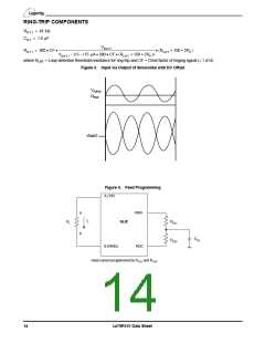
Ring-Trip Detection Equation
VBAT1 – 1
RRT1
I
I
= 8 µA for ON transition
= –20 µA for OFF transition
OFFSET
IRTD
=
---------------------------- + IOFFSET • 325
OFFSET
12
Le79R101 Data Sheet

 ZARLINK [ ZARLINK SEMICONDUCTOR INC ]