X9279
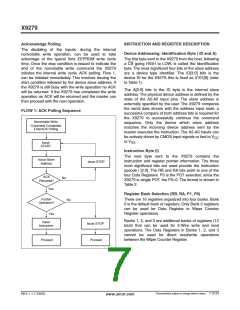
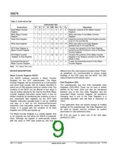
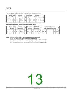
Table 3. Instruction Set
Instruction Set
Instruction
I3 I2 I1 I0 RB RA
P
P
Operation
1
0
Read Wiper Counter
Register
1
1
1
1
1
0
0
0
1
1
0
1
1
0
0
1
0
1
0
1
0
0
0
0
Read the contents of the Wiper Counter
Register
Write Wiper Counter
Register
0
0
0
0
Write new value to the Wiper Counter
Register
Read Data Register
1/0 1/0 1/0 1/0 Read the contents of the Data Register pointed
to by P1-P0 and RB-RA
Write Data Register
1/0 1/0 1/0 1/0 Write new value to the Data Register
pointed to by P1-P0 and RB-RA
XFR Data Register to
Wiper Counter Register
1/0 1/0
0
0
0
0
0
0
Transfer the contents of the Data Register
pointed to by RB-RA (Bank 0 only) to the Wiper
Counter Register
XFR Wiper Counter
Register to Data Register
1
0
1
0
1
1
0
0
1/0 1/0
Transfer the contents of the Wiper Counter
Register to the Register pointed to by RB-RA
(Bank 0 only)
Increment/Decrement
Wiper Counter Register
0
0
Enable Increment/decrement of the Wiper
Counter Register
Note: 1/0 = data is one or zero
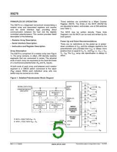
DEVICE DESCRIPTION
different from the value present at power-down. Power-
up guidelines are recommended to ensure proper
loadings of the DR0 value into the WCR. The DR0
value of Bank 0 is the default value.
Wiper Counter Register (WCR)
The X9279 contains contains a Wiper Counter
Register, for the DCP potentiometer. The Wiper
Counter Register can be envisioned as a 8-bit parallel
and serial load counter with its outputs decoded to
select one of 256 switches along its resistor array. The
contents of the WCR can be altered in four ways: it
may be written directly by the host via the Write Wiper
Counter Register instruction (serial load); it may be
written indirectly by transferring the contents of one of
four associated data registers via the XFR Data
Register instruction (parallel load); it can be modified
one step at a time by the Increment/Decrement
instruction (see Instruction section for more details).
Finally, it is loaded with the contents of its Data
Register zero (DR0) upon power-up.
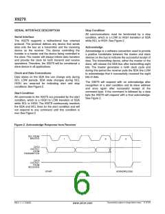
Data Registers (DR)
The potentiometer has four 8-bit nonvolatile Data
Registers (DR3-DR0). These can be read or written
directly by the host. Data can also be transferred
between any of the four Data Registers and the
associated Wiper Counter Register. All operations
changing data in one of the Data Registers is a
nonvolatile operation and will take a maximum of
10ms.
If the application does not require storage of multiple
settings for the potentiometer, the Data Registers can
be used as regular memory locations for system
parameters or user preference data.
The Wiper Counter Register is a volatile register; that
is, its contents are lost when the X9279 is powered-
down. Although the register is automatically loaded
with the value in DR0 upon power-up, this may be
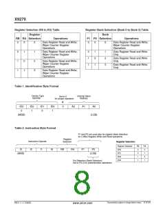
Bit [7:0] are used to store one of the 256 wiper
positions (0~255).
Characteristics subject to change without notice. 9 of 24
REV 1.1.7 2/6/03
www.xicor.com

 XICOR [ XICOR INC. ]