X4043/45
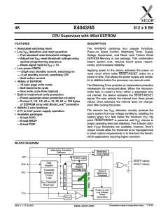
PRINCIPLES OF OPERATION
Power On Reset
nonvolatile control bits in the status register determine
the watchdog timer period. The microprocessor can
change these watchdog bits, or they may be “locked”
by tying the WP pin HIGH.
Application of power to the X4043/45 activates a Power
On Reset Circuit that pulls the RESET/RESET pin
active.This signal provides several benefits.
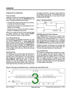
Figure 1. Watchdog Restart
.6µs
– It prevents the system microprocessor from starting
to operate with insufficient voltage.
1.3µs
SCL
SDA
– It prevents the processor from operating prior to sta-
bilization of the oscillator.
– It allows time for an FPGA to download its configura-
tion prior to initialization of the circuit.
Start
WDTReset
Stop
When V
exceeds the device V
threshold value
CC
TRIP
for 200ms (nominal) the circuit releases RESET/
RESET allowing the system to begin operation.
EEPROM Inadvertent Write Protection
When RESET/RESET goes active as a result of a low
voltage condition (V < V ), any in-progress com-
CC
TRIP
Low Voltage Monitoring
munications are terminated. While V
< V
, no
CC
TRIP
During operation, the X4043/45 monitors the V
level
CC
new communications are allowed and no nonvolatile
write operation can start. Nonvolatile writes in-progress
when RESET/RESET goes active are allowed to finish.
and asserts RESET/RESET if supply voltage falls
below a preset minimum V . The RESET/RESET
TRIP
signal prevents the microprocessor from operating in a
power fail or brownout condition. The RESET/RESET
signal remains active until the voltage drops below 1V.
Additional protection mechanisms are provided with
memory block lock and the Write Protect (WP) pin.
These are discussed elsewhere in this document.
It also remains active until V
returns and exceeds
CC
V
for 200ms.
TRIP
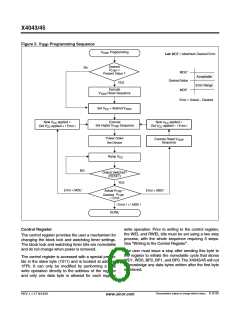
V
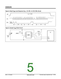
Programming
TRIP
Watchdog Timer
The X4043/45 is shipped with a standard V
thresh-
CC
The Watchdog Timer circuit monitors the microproces-
sor activity by monitoring the SDA and SCL pins. A
standard read or write sequence to any slave address
byte restarts the watchdog timer and prevents the
(RESET/RESET) signal going active. A minimum
sequence to reset the watchdog timer requires four
microprocessor intructions namely, a Start, Clock Low,
Clock High and Stop. (See Page 18) The state of two
old (V
) voltage. This value will not change over
TRIP
normal operating and storage conditions. However, in
applications where the standard V is not exactly
right, or if higher precision is needed in the V
value, the X4043/45 threshold may be adjusted. The
procedure is described below, and uses the application
of a high voltage control signal.
TRIP
TRIP
Figure 2. Set V
Level Sequence (V = desired V
values WEL bit set)
TRIP
CC
TRIP
V
3
= 15-18V
P
WP
0
1
2
3
4
5 6 7
0
1
2
3
4
5 6 7
0
1
2
4 5 6 7
SCL
SDA
A0h
01h
00h
Characteristics subject to change without notice. 3 of 25
REV 1.1.17 9/14/01
www.xicor.com

 XICOR [ XICOR INC. ]