Product Preview
WM8983
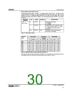
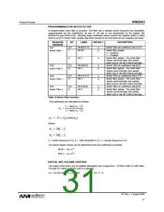
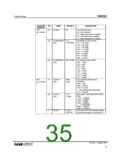
PROGRAMMABLE IIR NOTCH FILTER
A programmable notch filter is provided. This filter has a variable centre frequency and bandwidth,
programmable via two coefficients, a0 and a1. a0 and a1 are represented by the register bits
NFA0[13:0] and NFA1[13:0]. Because these coefficient values require four register writes to setup
there is an NFU (Notch Filter Update) flag which should be set only when all four registers are setup.
REGISTER
ADDRESS
BIT
LABEL
DEFAULT
DESCRIPTION
6:0
NFA0[13:7]
NFEN
Notch Filter a0 coefficient, bits [13:7]
R27
0
0
7
8
Notch filter enable:
0 = Disabled
1 = Enabled
Notch filter update. The notch filter
values used internally only update
when one of the NFU bits is set high.
Notch Filter a0 coefficient, bits [6:0]
Notch Filter 1
NFU
0
6:0
8
NFA0[6:0]
NFU
R28
0
0
Notch filter update. The notch filter
values used internally only update
when one of the NFU bits is set high.
Notch Filter a1 coefficient, bits [13:7]
Notch Filter 2
6:0
8
NFA1[13:7]
NFU
R29
0
0
Notch filter update. The notch filter
values used internally only update
when one of the NFU bits is set high.
Notch Filter a1 coefficient, bits [6:0]
Notch Filter 3
0-6
8
NFA1[6:0]
NFU
R30
0
0
Notch filter update. The notch filter
values used internally only update
when one of the NFU bits is set high.
Notch Filter 4
Table 15 Notch Filter Function
The coefficients are calculated as follows:
1− tan(wb / 2)
a0 =
1+ tan(wb / 2)
a1 = −(1+ a0 )cos(w0 )
Where:
w0 = 2πfc / fs
wb = 2πfb / fs
fc = centre frequency in Hz, fb = -3dB bandwidth in Hz, fs = sample frequency in Hz
The actual register values can be determined from the coefficients as follows:
NFA0 = -a0 x 213
NFA1 = -a1 x 212
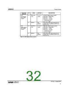
DIGITAL ADC VOLUME CONTROL
The output of the ADCs can be digitally attenuated over a range from –127dB to 0dB in 0.5dB steps.
The gain for a given eight-bit code X is given by:
0.5 × (G-255) dB for 1 ≤ G ≤ 255;
MUTE for G = 0
PP Rev 1.1 August 2005
31
w

 WOLFSON [ WOLFSON MICROELECTRONICS PLC ]