Product Preview
WM8983
ANALOGUE TO DIGITAL CONVERTER (ADC)
The WM8983 uses stereo multi-bit, oversampled sigma-delta ADCs. The use of multi-bit feedback
and high oversampling rates reduces the effects of jitter and high frequency noise. The ADC Full
Scale input level is proportional to AVDD1. With a 3.3V supply voltage, the full scale level is 1.0Vrms
Any voltage greater than full scale may overload the ADC and cause distortion.
.
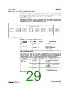
ADC DIGITAL FILTERS
The ADC filters perform true 24 bit signal processing to convert the raw multi-bit oversampled data
from the ADC to the correct sampling frequency to be output on the digital audio interface. The
digital filter path for each ADC channel is illustrated in Figure 18.
Figure 18 ADC Digital Filter Path
The ADCs are enabled by the ADCENL/R register bit.
REGISTER
ADDRESS
BIT
LABEL
DEFAULT
DESCRIPTION
R2
0
ADCENL
0
0
Enable ADC left channel:
0 = ADC disabled
Power
management 2
1 = ADC enabled
1
ADCENR
Enable ADC right channel:
0 = ADC disabled
1 = ADC enabled
Table 11 ADC Enable Control
The polarity of the output signal can also be changed under software control using the
ADCLPOL/ADCRPOL register bit. The oversampling rate of the ADC can be adjusted using the
ADCOSR register bit. With ADCOSR=0 the oversample rate is 64x which gives lowest power
operation and when ADCOSR=1 the oversample rate is 128x which gives best performance.
REGISTER
ADDRESS
BIT
LABEL
DEFAULT
DESCRIPTION
R14
ADC Control
0
ADCLPOL
0
ADC left channel polarity adjust:
0 = normal
1 = inverted
1
3
ADCRPOL
ADCOSR
0
0
ADC right channel polarity adjust:
0 = normal
1 = inverted
ADC oversample rate select:
0 = 64x (lower power)
1 = 128x (best performance)
Table 12 ADC Control
PP Rev 1.1 August 2005
29
w

 WOLFSON [ WOLFSON MICROELECTRONICS PLC ]