Product Preview
WM8983
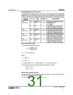
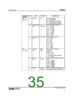
REGISTER
ADDRESS
BIT
LABEL
ALCSEL
DEFAULT
00
DESCRIPTION
R32
8:7
ALC function select
00 = ALC disabled
ALC Control
1
01 = Right channel ALC enabled
10 = Left channel ALC enabled
11 = Both channels ALC enabled
Set Maximum Gain of PGA
111 = +35.25dB
110 = +29.25dB
101 = +23.25dB
100 = +17.25dB
011 = +11.25dB
010 = +5.25dB
5:3
ALCMAXGAIN 111
(+35.25dB)
[2:0]
001 = -0.75dB
000 = -6.75dB
2:0
ALCMINGAIN
[2:0]
000 (-12dB)
Set minimum gain of PGA
000 = -12dB
001 = -6dB
010 = 0dB
011 = +6dB
100 = +12dB
101 = +18dB
110 = +24dB
111 = +30dB
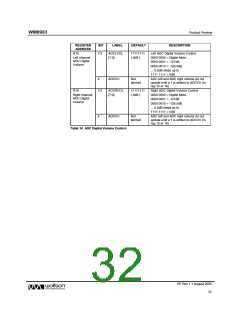
R33
7:4
3:0
ALCHLD
[3:0]
0000
ALC hold time before gain is
increased.
ALC Control
2
(0ms)
0000 = 0ms
0001 = 2.67ms
0010 = 5.33ms
… (time doubles with every step)
1111 = 43.691s
ALCLVL
[3:0]
1011
ALC target – sets signal level at ADC
input
(-12dB)
1111 = -1.5dBFS
1110 = -1.5dBFS
1101 = -3dBFS
1100 = -4.5dBFS
...... (-1.5dB steps)
0001 = -21dBFS
0000 = -22.5dBFS
8
ALCZC
0 (zero
cross off)
ALC uses zero cross detection circuit.
(not recommended for use with ALC)
PP Rev 1.1 August 2005
35
w

 WOLFSON [ WOLFSON MICROELECTRONICS PLC ]