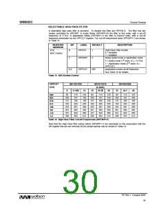
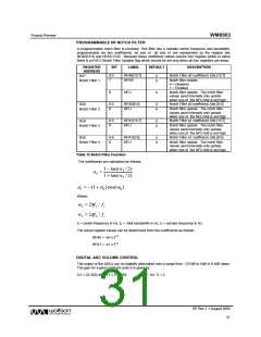
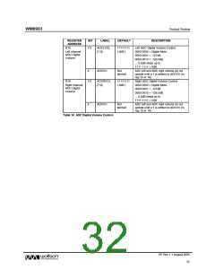
WM8983
Product Preview
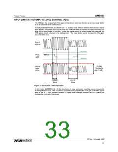
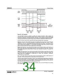
Figure 20 ALC Operation
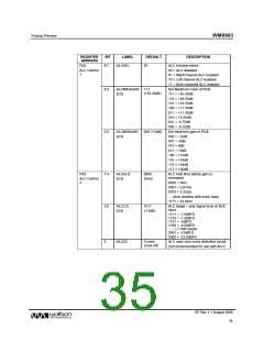
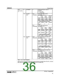
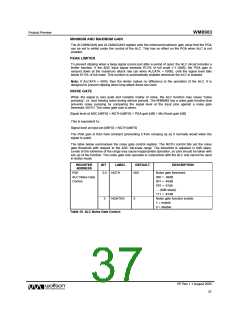
The ALC/Limiter function is enabled by setting the register bit ALCSEL. When enabled, the
recording volume can be programmed between –6dB and –28.5dB (relative to ADC full scale) using
the ALCLVL register bits. An upper limit for the PGA gain can be imposed by setting the ALCMAX
control bits and a lower limit for the PGA gain can be imposed by setting the ALCMIN control bits.
ALCHLD, ALCDCY and ALCATK control the hold, decay and attack times, respectively:
Hold time is the time delay between the peak level detected being below target and the PGA gain
beginning to ramp up. It can be programmed in power-of-two (2n) steps, e.g. 2.67ms, 5.33ms,
10.67ms etc. up to 43.7s. Alternatively, the hold time can also be set to zero. The hold time is not
active in limiter mode (ALCMODE = 1). The hold time only applies to gain ramp-up, there is no delay
before ramping the gain down when the signal level is above target.
Decay (Gain Ramp-Up) Time is the time that it takes for the PGA gain to ramp up and is given as a
time per gain step, time per 6dB change and time to ramp up over 90% of it’s range. The decay
time can be programmed in power-of-two (2n) steps, from 3.3ms/6dB, 6.6ms/6dB, 13.1ms/6dB, etc.
to 3.36s/6dB.
Attack (Gain Ramp-Down) Time is the time that it takes for the PGA gain to ramp down and is given
as a time per gain step, time per 6dB change and time to ramp down over 90% of it’s range. The
attack time can be programmed in power-of-two (2n) steps, from 832us/6dB, 1.66ms/6dB,
3.328us/6dB, etc. to 852ms/6dB.
NB, In peak limiter mode the gain control circuit runs approximately 4x faster to allow reduction of
fast peaks. Attack and Decay times for peak limiter mode are given below.
The hold, decay and attack times given in Table 17 are constant across sample rates so long as the
SR bits are set correctly. E.g. when sampling at 48kHz the sample rates stated in Table 17 will only
be correct if the SR bits are set to 000 (48kHz). If the actual sample rate was only 44.1kHz then the
hold, decay and attack times would be scaled down by 44.1/48.
Note: Zero cross function can affect these time constants, and is not recommended for use during
ALC operation.
PP Rev 1.1 August 2005
34
w

 WOLFSON [ WOLFSON MICROELECTRONICS PLC ]