WM8983
Product Preview
AUXILLIARY INPUTS
There are two auxiliary inputs, AUXL and AUXR which can be used for a variety of purposes such as
stereo line inputs or as a ‘beep’ input signal to be mixed with the outputs.
As signal inputs, AUXL/R inputs can be used as a line input to the input BOOST stage which has
adjustable gain of -12dB to +6dB in 3dB steps, with an additional "off" state (i.e. not connected to
ADC input). See the INPUT BOOST section for further details.
The AUXL/R inputs can also be mixed into the output channel mixers, with a gain of -15dB to +6dB
plus off.
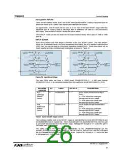
INPUT BOOST
Each of the stereo input PGA stages is followed by an input BOOST circuit. The input BOOST
circuit has 3 selectable inputs: the input microphone PGA output, the AUX amplifier output and the
L2/R2 input pin (can be used as a line input, bypassing the input PGA). These three inputs can be
mixed together and have individual gain boost/adjust as shown in Figure 16.
Figure 16 Input Boost Stage
The input PGA paths can have a +20dB boost (PGABOOSTL/R=1) , a 0dB pass through
(PGABOOSTL/R=0) or be completely isolated from the input boost circuit (INPPGAMUTEL/R=1).
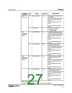
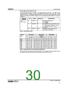
REGISTER
ADDRESS
BIT
LABEL
DEFAULT
DESCRIPTION
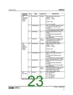
R47
8
PGABOOSTL
1
Boost enable for left channel input
PGA:
Left Input
BOOST
control
0 = PGA output has +0dB gain
through input BOOST stage.
1 = PGA output has +20dB gain
through input BOOST stage.
R48
8
PGABOOSTR
1
Boost enable for right channel input
PGA:
Right Input
BOOST
control
0 = PGA output has +0dB gain
through input BOOST stage.
1 = PGA output has +20dB gain
through input BOOST stage.
Table 6 Input BOOST Stage Control
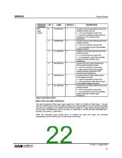
The Auxilliary amplifier path to the BOOST stages is controlled by the AUXL2BOOSTVOL[2:0] and
AUXR2BOOSTVOL[2:0] register bits. When AUXL2BOOSTVOL/AUXR2BOOSTVOL=000 this path
is completely disconnected from the BOOST stage. Settings 001 through to 111 control the gain in
3dB steps from -12dB to +6dB.
The L2/R2 path to the BOOST stage is controlled by the LIP2BOOSTVOL[2:0] and the
RIP2BOOSTVOL[2:0] register bits. When L2_2BOOSTVOL/R2_2BOOSTVOL=000 the L2/R2 input
pin is completely disconnected from the BOOST stage. Settings 001 through to 111 control the gain
in 3dB steps from -12dB to +6dB.
PP Rev 1.1 August 2005
26
w

 WOLFSON [ WOLFSON MICROELECTRONICS PLC ]