WM8983
Product Preview
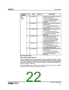
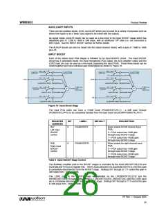
REGISTER
ADDRESS
BIT
LABEL
DEFAULT
DESCRIPTION
R44
0
LIP2INPPGA
1
Connect LIP pin to left channel input PGA
amplifier positive terminal.
Input
Control
0 = LIP not connected to input PGA
1 = input PGA amplifier positive terminal
connected to LIP (constant input
impedance)
1
2
LIN2INPPGA
L2_2INPPGA
1
0
Connect LIN pin to left channel input PGA
negative terminal.
0 = LIN not connected to input PGA
1 = LIN connected to input PGA amplifier
negative terminal.
Connect L2 pin to left channel input PGA
positive terminal.
0 = L2 not connected to input PGA
1 = L2 connected to input PGA amplifier
positive terminal (constant input
impedance).
4
RIP2INPPGA
1
Connect RIP pin to right channel input
PGA amplifier positive terminal.
0 = RIP not connected to input PGA
1 = right channel input PGA amplifier
positive terminal connected to RIP
(constant input impedance)
5
6
RIN2INPPGA
R2_2INPPGA
1
0
Connect RIN pin to right channel input
PGA negative terminal.
0 = RIN not connected to input PGA
1 = RIN connected to right channel input
PGA amplifier negative terminal.
Connect R2 pin to right channel input PGA
positive terminal.
0 = R2 not connected to input PGA
1 = R2 connected to input PGA amplifier
positive terminal (constant input
impedance).
Table 4 Input PGA Control
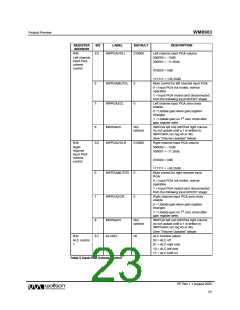
INPUT PGA VOLUME CONTROLS
The input microphone PGAs have a gain range from -12dB to +35.25dB in 0.75dB steps. The gain
from the LIN/RIN input to the PGA output and from the L2/R2 amplifier to the PGA output are always
common and controlled by the register bits INPPGAVOLL/R[5:0]. These register bits also affect the
LIP pin when LIP2INPPGA=1, the L2 pin when L2_2INPPGA=1, the RIP pin when RIP2INPPGA=1
and the L2 pin when L2_2INPPGA=1.
When the Automatic Level Control (ALC) is enabled the input PGA gains are controlled
automatically and the INPPGAVOLL/R bits should not be used.
PP Rev 1.1 August 2005
22
w

 WOLFSON [ WOLFSON MICROELECTRONICS PLC ]