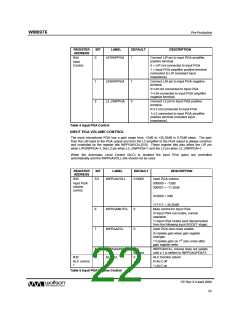
WM8976
Pre-Production
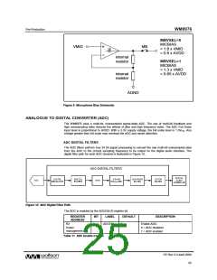
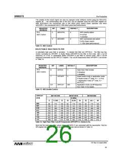
The polarity of the output signal can also be changed under software control using the ADCLPOL
register bit. The oversampling rate of the ADC can be adjusted using the ADCOSR register bit.
With ADCOSR=0 the oversample rate is 64x which gives lowest power operation and when
ADCOSR=1 the oversample rate is 128x which gives best performance.
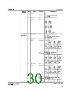
REGISTER
ADDRESS
BIT
LABEL
DEFAULT
DESCRIPTION
R14
ADC Control
0
ADCLPOL
0
ADC polarity adjust:
0=normal
1=inverted
3
ADCOSR
0
ADC oversample rate select:
0=64x (lower power)
1=128x (best performance)
Table 12 ADC Control
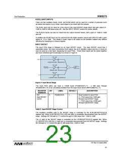
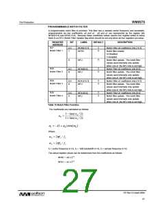
SELECTABLE HIGH PASS FILTER
A selectable high pass filter is provided. To disable this filter set HPFEN=0. The filter has two
modes controlled by HPFAPP. In Audio Mode (HPFAPP=0) the filter is first order, with a cut-off
frequency of 3.7Hz. In Application Mode (HPFAPP=1) the filter is second order, with a cut-off
frequency selectable via the HPFCUT register. The cut-off frequencies when HPFAPP=1 are shown
in Table 14.
REGISTER
ADDRESS
BIT
LABEL
DEFAULT
DESCRIPTION
High Pass Filter Enable
R14
ADC Control
8
7
HPFEN
1
0=disabled
1=enabled
HPFAPP
0
Select audio mode or application mode
0=Audio mode (1st order, fc = ~3.7Hz)
1=Application mode (2nd order, fc =
HPFCUT)
6:4
Table 13 ADC Enable Control
HPFCUT
000
Application mode cut-off frequency
See Table 14 for details.
HPFCUT
[2:0]
SR=101/100
SR=011/010
fs (kHz)
22.05
SR=001/000
44.1
8
11.025
12
16
24
32
48
000
001
010
011
100
101
110
111
82
113
141
180
225
281
360
450
563
122
153
156
245
306
392
490
612
82
113
141
180
225
281
360
450
563
122
153
156
245
306
392
490
612
82
113
141
180
225
281
360
450
563
122
153
156
245
306
392
490
612
102
131
163
204
261
327
408
102
131
163
204
261
327
408
102
131
163
204
261
327
408
Table 14 High Pass Filter Cut-off Frequencies (HPFAPP=1). Values in Hz.
Note that the High Pass filter values (when HPFAPP=1) are calculated with the assumption that the
SR register bits are set correctly for the actual sample rate as shown in Table 14.
PP Rev 3.0 April 2006
26
w

 WOLFSON [ WOLFSON MICROELECTRONICS PLC ]