Pre-Production
WM8976
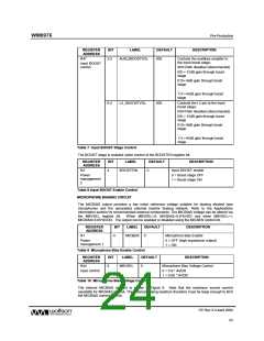
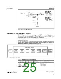
MBVSEL=0
MICBIAS
= 1.8 x VMID
= 0.9 x AVDD
VMID
MB
internal
resistor
MBVSEL=1
MICBIAS
= 1.3 x VMID
= 0.65 x AVDD
internal
resistor
AGND
Figure 9 Microphone Bias Schematic
ANALOGUE TO DIGITAL CONVERTER (ADC)
The WM8976 uses a multi-bit, oversampled sigma-delta ADC. The use of multi-bit feedback and
high oversampling rates reduces the effects of jitter and high frequency noise. The ADC Full Scale
input level is proportional to AVDD. With a 3.3V supply voltage, the full scale level is 1.0Vrms. Any
voltage greater than full scale may overload the ADC and cause distortion.
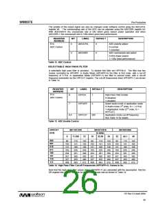
ADC DIGITAL FILTERS
The ADC filters perform true 24 bit signal processing to convert the raw multi-bit oversampled data
from the ADC to the correct sampling frequency to be output on the digital audio interface. The
digital filter path for each ADC channel is illustrated in Figure 10.
Figure 10 ADC Digital Filter Path
The ADC is enabled by the ADCENL/R register bit.
REGISTER
ADDRESS
BIT
LABEL
DEFAULT
DESCRIPTION
Enable ADC:
R2
0
ADCENL
0
Power
management 2
0 = ADC disabled
1 = ADC enabled
Table 11 ADC Enable Control
PP Rev 3.0 April 2006
25
w

 WOLFSON [ WOLFSON MICROELECTRONICS PLC ]