WM8976
Pre-Production
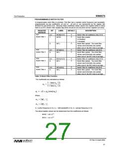
NOTCH FILTER WORKED EXAMPLE
The following example illustrates how to calculate the a0 and a1 coefficients for a desired centre
frequency and -3dB bandwidth.
fc = 1000 Hz
fb = 100 Hz
fs = 48000 Hz
w0 = 2πfc / fs
wb = 2πfb / fs
2π
2π
=
=
x (1000 / 48000) = 0.1308996939 rads
x (100 / 48000) = 0.01308996939 rads
1− tan(wb / 2)
1+ tan(wb / 2)
1− tan(0.01308996939/ 2)
a0 =
1+ tan(0.01308996939/ 2) = 0.9869949627
=
a1 = −(1+ a0 )cos(w0 )
− (1+ 0.9869949627)cos(0.1308996939)
=
=
-
1.969995945
NFA0 = -a0 x 213 = -8085 (rounded to nearest whole number)
NFA1 = -a1 x 212 = 8069 (rounded to nearest whole number)
These values are then converted to a 14-bit sign / magnitude notation:
NFA0[13] = 1; NFA0[12:0] = 13’h1F95; NFA0 = 14’h3F95 = 14’b11111110010101
NFA1[13] = 0; NFA1[12:0] = 13’h1F85; NFA1 = 14’h1F85 = 14’b01111110000101
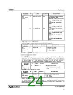
DIGITAL ADC VOLUME CONTROL
The output of the ADC can be digitally attenuated over a range from –127dB to 0dB in 0.5dB steps.
The gain for a given eight-bit code X is given by:
0.5 × (G-255) dB for 1 ≤ G ≤ 255;
MUTE for G = 0
REGISTER
ADDRESS
BIT
LABEL
DEFAULT
DESCRIPTION
R15
7:0
ADCVOLL
[7:0]
11111111
( 0dB )
ADC Digital Volume Control
0000 0000 = Digital Mute
0000 0001 = -127dB
0000 0010 = -126.5dB
... 0.5dB steps up to
ADC Digital
Volume
1111 1111 = 0dB
8
ADCVU
Not
latched
ADC volume does not update until a 1 is
written to ADCVU
Table 16 ADC Digital Volume Control
PP Rev 3.0 April 2006
28
w

 WOLFSON [ WOLFSON MICROELECTRONICS PLC ]