WM8976
Pre-Production
REGISTER
ADDRESS
BIT
LABEL
DEFAULT
DESCRIPTION
R44
0
LIP2INPPGA
1
Connect LIP pin to input PGA amplifier
positive terminal.
Input
Control
0 = LIP not connected to input PGA
1 = input PGA amplifier positive terminal
connected to LIP (constant input
impedance)
1
2
LIN2INPPGA
L2_2INPPGA
1
0
Connect LIN pin to input PGA negative
terminal.
0=LIN not connected to input PGA
1=LIN connected to input PGA amplifier
negative terminal.
Connect L2 pin to input PGA positive
terminal.
0=L2 not connected to input PGA
1=L2 connected to input PGA amplifier
positive terminal (constant input
impedance).
Table 4 Input PGA Control
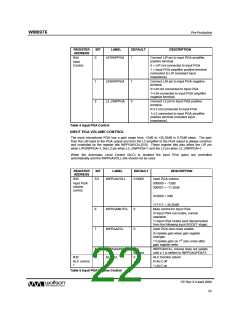
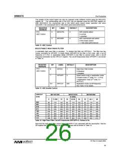
INPUT PGA VOLUME CONTROL
The input microphone PGA has a gain range from -12dB to +35.25dB in 0.75dB steps. The gain
from the LIN input to the PGA output and from the L2 amplifier to the PGA output is always common
and controlled by the register bits INPPGAVOLL[5:0]. These register bits also affect the LIP pin
when LIP2INPPGA=1, the L2 pin when L2_2INPPGA=1 and the L2 pin when L2_2INPPGA=1.
When the Automatic Level Control (ALC) is enabled the input PGA gains are controlled
automatically and the INPPGAVOLL bits should not be used.
REGISTER
ADDRESS
BIT
LABEL
DEFAULT
DESCRIPTION
Input PGA volume
R45
5:0
INPPGAVOLL
010000
Input PGA
volume
control
000000 = -12dB
000001 = -11.25db
.
010000 = 0dB
.
111111 = 35.25dB
Mute control for input PGA:
6
7
INPPGAMUTEL
INPPGAZCL
0
0
0=Input PGA not muted, normal
operation
1=Input PGA muted (and disconnected
from the following input BOOST stage).
Input PGA zero cross enable:
0=Update gain when gain register
changes
1=Update gain on 1st zero cross after
gain register write.
8
8
INPPGAUPDATE Not
latched
INPPGAVOLL volume does not update
until a 1 is written to INPPGAUPDATE
R32
ALCSEL
0
ALC function select:
0=ALC off
ALC control
1
1=ALC on
Table 5 Input PGA Volume Control
PP Rev 3.0 April 2006
22
w

 WOLFSON [ WOLFSON MICROELECTRONICS PLC ]