Pre-Production
WM8976
AUXILLIARY INPUTS
There are two auxilliary inputs, AUXL and AUXR which can be used for a variety of purposes such
as stereo line inputs or as a ‘beep’ input signal to be mixed with the outputs.
The AUXL input can be used as a line input to the input BOOST stage which has gain adjust of -
12dB to +6dB in 3dB steps (plus off). See the INPUT BOOST section for further details.
The AUXL/R inputs can also be mixed into the output channel mixers, with a gain of -15dB to +6dB
plus off.
In addition the AUXR input can be summed into the Right speaker output path (ROUT2) with a gain
adjust of -15 to +6dB. This allows a ‘beep’ input to be output on the speaker outputs only without
affecting the headphone or lineout signals.
INPUT BOOST
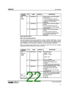
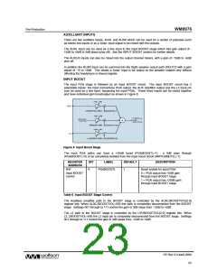
The input PGA stage is followed by an input BOOST circuit. The input BOOST circuit has 3
selectable inputs: the input microphone PGA output, the AUX amplifier output and the L2 input pin
(can be used as a line input, bypassing the input PGA). These three inputs can be mixed together
and have individual gain boost/adjust as shown in Figure 8.
Figure 8 Input Boost Stage
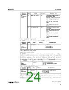
The input PGA paths can have a +20dB boost (PGABOOSTL=1) , a 0dB pass through
(PGABOOSTL=0) or be completely isolated from the input boost circuit (INPPGAMUTEL=1).
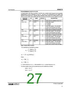
REGISTER
ADDRESS
BIT
LABEL
DEFAULT
DESCRIPTION
R47
8
PGABOOSTL
1
Boost enable for input PGA:
Input BOOST
control
0 = PGA output has +0dB gain
through input BOOST stage.
1 = PGA output has +20dB gain
through input BOOST stage.
Table 6 Input BOOST Stage Control
The Auxilliary amplifier path to the BOOST stage is controlled by the AUXL2BOOSTVOL[2:0]
register bits. When AUXL2BOOSTVOL=000 this path is completely disconnected from the BOOST
stage. Settings 001 through to 111 control the gain in 3dB steps from -12dB to +6dB.
The L2 path to the BOOST stage is controlled by the LIP2BOOSTVOL[2:0] register bits. When
L2_2BOOSTVOL=000 the L2 input pin is completely disconnected from the BOOST stage. Settings
001 through to 111 control the gain in 3dB steps from -12dB to +6dB.
PP Rev 3.0 April 2006
23
w

 WOLFSON [ WOLFSON MICROELECTRONICS PLC ]