Pre-Production
WM8959
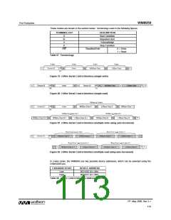
These modes are shown in the section below. Terminology used in the following figures:
TERMINOLOGY
DESCRIPTION
Start Condition
Repeated start
Acknowledge
Stop Condition
S
Sr
A
P
RW
ReadNotWrite
0 = Write
1 = Read
Table 67 Terminology
Figure 79 2-Wire Serial Control Interface (single write)
RW
RW
S
Device ID
A
Index
A
Sr
Device ID
A
MSByte Data
A
LSByte Data
A
P
(0)
(1)
Figure 80 2-Wire Serial Control Interface (single read)
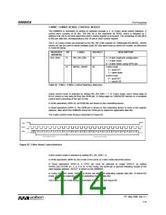
Figure 81 2-Wire Serial Control Interface (multiple write using auto-increment)
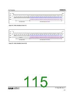
Figure 82 2-Wire Serial Control Interface (multiple read using auto-increment)
In 2-wire mode, the WM8959 has two possible device addresses, which can be selected using the
CSB/ADDR pin.
CSB/ADDR STATE
DEVICE ADDRESS
0011010 (0 x 34h)
0011011 (0 x 36h)
Low
High
Table 68 2-Wire Control Interface Address Selection
PP, May 2008, Rev 3.1
113
w

 WOLFSON [ WOLFSON MICROELECTRONICS PLC ]