WM8959
Pre-Production
PLL
The integrated PLL can be used to generate SYSCLK for the WM8959 from a wide range of MCLK
reference frequencies. The PLL is enabled by the PLL_ENA register bit. If required, the input
reference clock can be divided by 2 by setting the register bit PRESCALE.
The PLL frequency ratio R is equal to f2/f1 (see Figure 78). This ratio is the real number represented
by register fields PLLN and PLLK, where PLLN is an integer (LSB = 1) and PLLK is the fractional
portion of the number (MSB = 0.5). The fractional portion is only valid when enabled by the field
SDM. De-selection of fractional mode results in lower power consumption.
For PLL stability, input frequencies and divisions must be chosen so that 5 ≤ PLLN ≤ 13. Best
performance is achieved for 7 ≤ N ≤9. Also, the PLL performs best when f2 is set between 90MHz
and 100MHz.
If PLLK is regarded as a 16-bit integer (instead of a fractional quantity), then PLLN and PLLK may be
determined as follows:
•
•
PLLN = int R
PLLK = int (216 (R - PLLN))
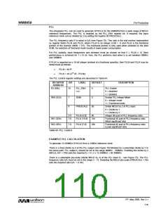
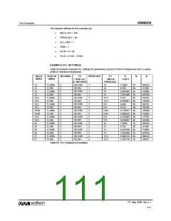
The PLL Control register settings are described in Table 64.
REGISTER
ADDRESS
BIT
LABEL
DEFAULT
DESCRIPTION
R2 (02h)
15
PLL_ENA
(rw)
0
PLL Enable
0 = disabled
1 = enabled
R60 (3Ch)
7
6
SDM
0
Enable PLL Integer Mode
0 = Integer mode
1 = Fractional mode
PRESCALE
0b
Divide MCLK by 2 at PLL input
0 = Divide by 1
1 = Divide by 2
3:0
7:0
PLLN [3:0]
8h
Integer (N) part of PLL frequency ratio.
R61 (3Dh)
R62 (3Eh)
PLLK [15:8]
31h
Fractional (K) part of PLL frequency ratio.
(Most significant bits)
7:0
PLLK [7:0]
26h
Fractional (K) part of PLL frequency ratio.
(Least significant bits)
Table 64 PLL Control
EXAMPLE PLL CALCULATION
To generate 12.288MHz SYSCLK from a 12MHz reference clock:
There is a fixed divide by 4 at the PLL output (see Figure 78) followed by a selectable divide by 2 in
the same path. PLL output f2 should be set in the range 90MHz - 100MHz. Enabling the divide by 2
(MCLK_DIV = 10b) sets the required f2 = 4 x 2 x 12.288MHz = 98.304MHz.
There is a selectable pre-scale (divide MCLK by 2) at the PLL input (f1 - see Figure 75). The PLL
frequency ratio f2/f1 must be set in the range 5 - 13. Disabling the MCLK pre-scale (PRESCALE = 0b)
sets the required ratio f2/f1 = 8.192.
PP, May 2008, Rev 3.1
110
w

 WOLFSON [ WOLFSON MICROELECTRONICS PLC ]