Pre-Production
WM8904
PCM operation is supported in DSP interface mode. WM8904 ADC data that is output on the Left
Channel will be read as mono PCM data by the receiving equipment. Mono PCM data received by the
WM8904 will be treated as Left Channel data. This data may be routed to the Left/Right DACs as
described in the “Digital Mixing” section.
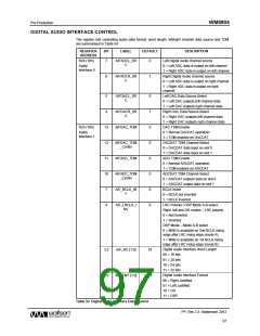
AUDIO DATA FORMATS (TDM MODE)
TDM is supported in master and slave mode and is enabled by register bits AIFADC_TDM and
AIFDAC_TDM. All audio interface data formats support time division multiplexing (TDM) for ADC and
DAC data.
Two time slots are available (Slot 0 and Slot 1), selected by register bits AIFADC_TDM_CHAN and
AIFDAC_TDM_CHAN which control time slots for the ADC data and the DAC data.
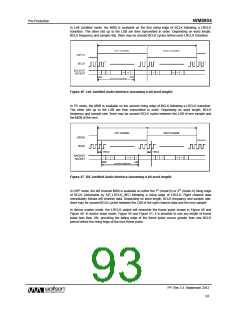
When TDM is enabled, the ADCDAT pin will be tri-stated immediately before and immediately after
data transmission, to allow another audio device to drive this signal line for the remainder of the
sample period. It is important that two audio devices do not attempt to drive the data pin
simultaneously, as this could result in a short circuit. See “Audio Interface Timing” for details of the
ADCDAT output relative to BCLK signal. Note that it is possible to ensure a gap exists between
transmissions by setting the transmitted word length to a value higher than the actual length of the
data. For example, if 32-bit word length is selected where only 24-bit data is available, then the
WM8904 interface will tri-state after transmission of the 24-bit data; this creates an 8-bit gap after the
WM8904’s TDM transmission slot.
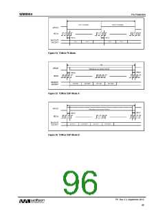
When TDM is enabled, BCLK frequency must be high enough to allow data from both time slots to be
transferred. The relative timing of Slot 0 and Slot 1 depends upon the selected data format as shown
in Figure 52 to Figure 56.
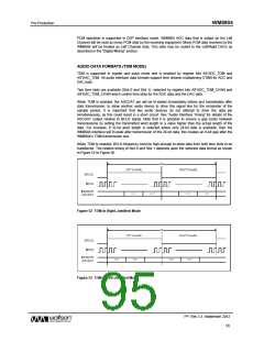
Figure 52 TDM in Right-Justified Mode
Figure 53 TDM in Left-Justified Mode
PP, Rev 3.3, September 2012
95
w

 WOLFSON [ WOLFSON MICROELECTRONICS PLC ]