WM8904
Pre-Production
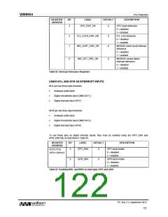
INTERRUPTS
The Interrupt Controller has multiple inputs; these include the GPIO input pins and the MICBIAS
current detection circuits. Any combination of these inputs can be used to trigger an Interrupt (IRQ)
event.
WM8904 interrupt events may be triggered in response to external GPIO inputs, FLL Lock status,
MICBIAS status or Write Sequencer status. Note that the GPIO inputs (including GPI7 and GPI8) are
only supported as interrupt events when the respective pin is configured as a GPIO input.
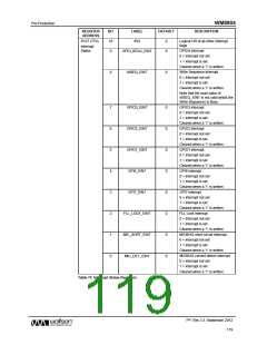
There is an Interrupt Status field associated with each of the IRQ inputs. These are contained in the
Interrupt Status Register (R127), as described in Table 79. The status of the IRQ inputs can be read
from this register at any time, or in response to the Interrupt Output being signalled via a GPIO pin.
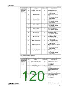
Individual mask bits can select or deselect different functions from the Interrupt controller. These are
listed within the Interrupt Status Mask register (R128), as described in Table 80. Note that the
Interrupt Status fields remain valid, even when masked, but the masked bits will not cause the
Interrupt (IRQ) output to be asserted.
The Interrupt (IRQ) output represents the logical ‘OR’ of all unmasked IRQ inputs. The bits within the
Interrupt Status register (R127) are latching fields and, once set, are not reset until a ‘1’ is written to
the respective register bit in the Interrupt Status Register. The Interrupt (IRQ) output is not reset until
each of the unmasked IRQ inputs has been reset.
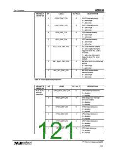
Each of the IRQ inputs can be individually inverted in the Interrupt function, enabling either active
high or active low behaviour on each IRQ input. The polarity inversion is controlled using the bits
contained in the Interrupt Polarity register (R129).
Each of the IRQ inputs can be debounced to ensure that spikes and transient glitches do not assert
the Interrupt Output. This is selected using the bits contained in the Interrupt Debounce Register
(R130).
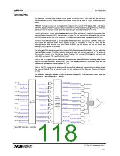
The WM8904 Interrupt Controller circuit is illustrated in Figure 60. The associated control fields are
described in Table 79 through to Table 82.
Figure 60 Interrupt Controller
PP, Rev 3.3, September 2012
118
w

 WOLFSON [ WOLFSON MICROELECTRONICS PLC ]