Pre-Production
WM8904
GENERAL PURPOSE INPUT/OUTPUT (GPIO)
The WM8904 provides four multi-function pins which can be configured to provide a number of
different functions. These are digital input/output pins on the DBVDD power domain. The GPIO pins
are:
IRQ/GPIO1
GPIO2
GPIO3
BCLK/GPIO4
Each general purpose I/O pin can be configured to be a GPIO input or configured as one of a number
of output functions. Signal de-bouncing can be selected on GPIO input pins for use with jack/button
detect applications. Table 74 lists the functions that are available on each of the GPIO pins.
GPIO PINS
GPIO Pin Function
GPIO input
IRQ / GPIO1
GPIO2
GPIO3
BCLK / GPIO4
Yes
Yes
Yes
Yes
(including jack/button detect)
GPIO output
Yes
No
Yes
No
Yes
No
Yes
Yes
Yes
Yes
Yes
Yes
BCLK
Interrupt (IRQ)
Yes
Yes
Yes
Yes
Yes
Yes
Yes
Yes
Yes
Yes
Yes
Yes
MICBIAS current detect
MICBIAS short-circuit detect
Digital microphone interface
(DMIC clock output)
FLL Lock output
Yes
Yes
Yes
Yes
Yes
Yes
Yes
Yes
FLL Clock output
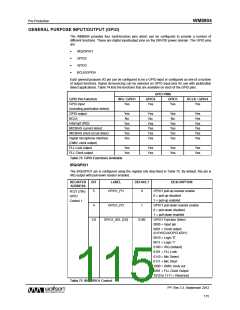
Table 74 GPIO Functions Available
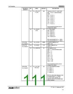
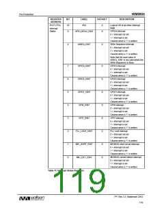
IRQ/GPIO1
The IRQ/GPIO1 pin is configured using the register bits described in Table 75. By default, this pin is
IRQ output with pull-down resistor enabled.
REGISTER
ADDRESS
BIT
LABEL
DEFAULT
DESCRIPTION
GPIO1 pull-up resistor enable
0 = pull-up disabled
5
GPIO1_PU
0
R121 (79h)
GPIO
1 = pull-up enabled
Control 1
GPIO1 pull-down resistor enable
0 = pull-down disabled
1 = pull-down enabled
GPIO1 Function Select
0000 = Input pin
4
GPIO1_PD
1
3:0
GPIO1_SEL [3:0]
0100
0001 = Clock output
(f=SYSCLK/OPCLKDIV)
0010 = Logic '0'
0011 = Logic '1'
0100 = IRQ (default)
0101 = FLL Lock
0110 = Mic Detect
0111 = Mic Short
1000 = DMIC clock out
1001 = FLL Clock Output
1010 to 1111 = Reserved
Table 75 IRQ/GPIO1 Control
PP, Rev 3.3, September 2012
115
w

 WOLFSON [ WOLFSON MICROELECTRONICS PLC ]