Pre-Production
WM8904
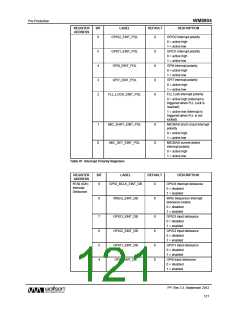
BCLK/GPIO4
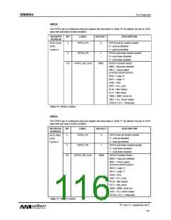
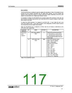
The BCLK/GPIO4 pin is configured using the register bits described in Table 78. By default, this pin
provides the BCLK function associated with the Digital Audio Interface. The BCLK function can
operate in slave mode (BCLK input) or in master mode (BCLK output), depending on the BCLK_DIR
register bit as described in the “Digital Audio Interface” section.
It is possible to configure the BCLK/GPIO4 pin to provide various GPIO functions; in this case, the
BCLK function is provided using the MCLK pin. Note that the BCLK function is always in slave mode
(BCLK input) in this mode.
To select the GPIO4 functions, it is required to set BCLK_DIR = 0 (see Table 56) and to set
GPIO_BCLK_MODE_ENA = 1 (see Table 78 below). In this configuration, the MCLK input is used as
the bit-clock (BCLK) for the Digital Audio Interface.
When the BCLK/GPIO4 pin is configured as GPIO4, then the pin function is determined by the
GPIO_BCLK_SEL register field.
REGISTER
ADDRESS
BIT
LABEL
DEFAULT
DESCRIPTION
Selects BCLK/GPIO4 pin function
0 = BCLK/GPIO4 is used as BCLK
7
GPIO_BCLK_MODE_
ENA
0
R124 (7Ch)
GPIO
1 = BCLK/GPIO4 is used as GPIO.
MCLK provides the BCLK in the AIF
in this mode.
Control 4
GPIO_BCLK function select:
0000 = Input Pin (default)
3:0
GPIO_BCLK_SEL
[3:0]
0000
0001 = Clock output
(f=SYSCLK/OPCLKDIV)
0010 = Logic '0'
0011 = Logic '1'
0100 = IRQ
0101 = FLL Lock
0110 = Mic Detect
0111 = Mic Short
1000 = DMIC clock out
1001 = FLL Clock Output
1010 to 1111 = Reserved
Table 78 BCLK/GPIO4 Control
PP, Rev 3.3, September 2012
117
w

 WOLFSON [ WOLFSON MICROELECTRONICS PLC ]