Production Data
WM8352
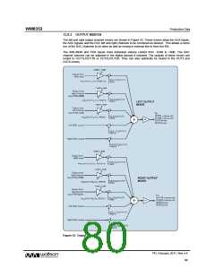
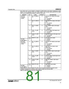
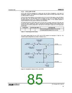
Each output mixer can be enabled or disabled by writing either to the power management control
register or to the respective mixer’s own control register. Each analogue signal going into the output
mixers can be independently enabled or muted for each mixer.
ADDRESS
R88 (58h)
BIT
LABEL
DEFAULT
DESCRIPTION
0
INL_TO_MIXOU
TL
0
Left input PGA output to left output
mixer
Left Mixer
Control
0 = not selected
1 = selected
1
2
INR_TO_MIXOU
TL
0
0
Right input PGA output to left output
mixer
0 = not selected
1 = selected
IN3L_TO_MIXO
UTL
IN3L amplifier output to left output
mixer:
0 = not selected
1 = selected
11
12
DACL_TO_MIX
OUTL
0
0
0
0
Left DAC output to left output mixer
0 = not selected
1 = selected
DACR_TO_MIX
OUTL
Right DAC output to left output mixer
0 = not selected
1 = selected
15
0
MIXOUTL_ENA
Left output mixer enable
0 = disabled
R9 (09h)
1= enabled
Power Mgmt 2
R89 (59h)
0
1
3
INL_TO_MIXOU
TR
Left input PGA output to right output
mixer
Right Mixer
Control
0 = not selected
1 = selected
INR_TO_MIXOU
TR
0
0
Right input PGA output to right
output mixer
0 = not selected
1 = selected
IN3L_TO_MIXO
UTR
IN3L amplifier output to right output
mixer:
0 = not selected
1 = selected
11
12
DACL_TO_MIX
OUTR
0
0
Left DAC output to right output mixer
0 = not selected
1 = selected
DACR_TO_MIX
OUTR
Right DAC output to right output
mixer
0 = not selected
1 = selected
15
1
MIXOUTR_ENA
0
Right output mixer enable
0 = disabled
R9 (09h)
1 = enabled
Power Mgmt 2
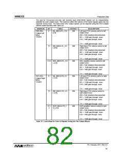
Note: MIXOUTL_ENA and MIXOUTR_ENA can be accessed through two separate control
registers. Reading from or writing to either register location has the same effect.
Table 38 Selecting Signals into the Output Mixers
PD, February 2011, Rev 4.4
81
w

 WOLFSON [ WOLFSON MICROELECTRONICS PLC ]