Production Data
WM8352
13.8 OUTPUT SIGNAL PATH
The analogue output pins produce audio signals to drive headphones, line-out connections and/or
external loudspeaker amplifiers. These pins include:
.
.
.
OUT1L and OUT1R
OUT2L and OUT2R
OUT3 and OUT4
OUT1L, OUT1R, OUT2L and OUT2R have individual analogue volume PGAs with -57dB to +6dB
ranges. AC-coupled and Capless headphone drive modes are available. Common mode noise
rejection is possible using the HPCOM connection.
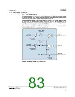
OUT3 and OUT4 can be configured as a stereo line out (OUT3 is left output and OUT4 is right
output). OUT3 and OUT4 can also be used as a Vmid buffer to provide a “ground” reference for
headphone outputs, eliminating the need for DC blocking capacitors.
Alternatively, OUT4 can be used to provide a mono mix of left and right channels.
All analogue output pins are powered through the HPVDD and HPGND pins.
Each output can drive a headphone load down to 16Ω.
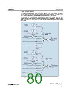
There are four output mixers in the output signal path: the left and right channel mixers which control
the signals to headphone (and optionally the line outputs) and also dedicated OUT3 and OUT4
mixers.
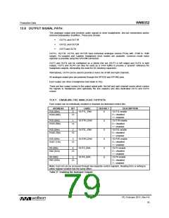
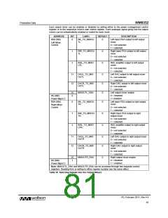
13.8.1 ENABLING THE ANALOGUE OUTPUTS
Each output can be individually enabled or disabled via dedicated control bits.
ADDRESS
R10 (0Ah)
BIT
0
LABEL
DEFAULT
DESCRIPTION
OUT1L enable
OUT1L_ENA
0
0 = disabled
1 = enabled
OUT1R enable
0 = disabled
1 = enabled
OUT2L enable
0 = disabled
1 = enabled
OUT2R enable
0 = disabled
1 = enabled
OUT3 enable
0 = disabled
1 = enabled
OUT4 enable
0 = disabled
1 = enabled
R104 (68h)
15
R10 (0Ah)
R105 (69h)
1
OUT1R_ENA
OUT2L_ENA
OUT2R_ENA
OUT3_ENA
OUT4_ENA
0
0
0
0
0
15
R10 (0Ah)
R106 (70h)
2
15
R10 (0Ah)
R107 (71h)
3
15
R9 (09h)
4
R92 (5Ch)
15
R9 (09h)
5
R93 (5Dh)
15
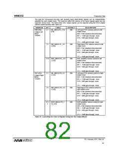
Note: Each bit can be accessed through two separate control registers. Reading from or writing to
either register location has the same effect.
Table 37 Enabling the Analogue Outputs
PD, February 2011, Rev 4.4
79
w

 WOLFSON [ WOLFSON MICROELECTRONICS PLC ]