WM8352
Production Data
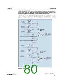
13.7.4 DAC OUTPUT PHASE AND MONO MIXING
The digital audio data is converted to oversampled bit streams in the on-chip 24-bit digital
interpolation filters. The bitstream data enters two multi-bit, sigma-delta DACs, which convert them to
high quality analogue audio signals. The multi-bit DAC architecture reduces high frequency noise and
sensitivity to clock jitter. It also uses a Dynamic Element Matching technique for high linearity and
low distortion.
In normal operation, the left and right channel digital audio data is converted to analogue in two
separate DACs. It is also possible for the DACs to output a mono mix of left and right channels,
using DAC_MONO. Both DACs must be enabled for this mono mix to function.
REGISTER
ADDRESS
BIT
LABEL
DEFAULT
DESCRIPTION
R48 (30h) DAC
Control
13
DAC_MONO
0
Adds left and right channel and
halves the resulting output to
create a mono output
1
0
DACL_DATINV
DACR_DATINV
0
0
DAC data left channel polarity
0 = Normal
1 = Inverted
DAC data right channel polarity
0 = Normal
1 = Inverted
Table 35 DAC Mono Mix and Phase Invert Select
13.7.5 DAC STOPBAND ATTENUATION
The DAC digital filter type is selected by the DAC_SB_FILT register bit as shown in Table 36.
REGISTER
ADDRESS
BIT
12
LABEL
DEFAULT
DESCRIPTION
R59 (3Bh)
DAC_SB_FILT
0
Selects DAC filter characteristics
0 = Normal mode
DAC Digital
Control
1 = Sloping stopband mode
Table 36 DAC Filter Selection
PD, February 2011, Rev 4.4
78
w

 WOLFSON [ WOLFSON MICROELECTRONICS PLC ]