Production Data
WM8352
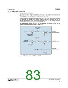
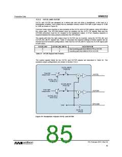
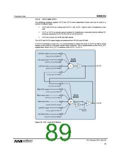
13.9.2 OUT2L AND OUT2R
OUT2L and OUT2R are designed as a stereo pair and can drive a headphone, a line load or a
loudspeaker amplifier. Each output has an analogue volume control PGA with a gain range of -57dB
to +6dB as shown in Figure 45.
Common mode noise rejection is also possible on the OUT2L and OUT2R outputs, using HPCOM as
the return path. The HPCOM feature must be enabled via the OUT2_FB register field and the
HPCOM connection must be AC coupled to the headphone output. A 4.7uF coupling capacitor is
required between the noisy ground connection the HPCOM pin.
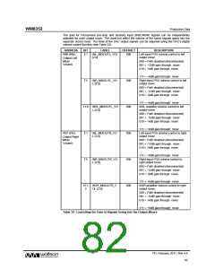
The signal path from the right output mixer to OUT2R can be inverted, using the OUT2R_INV and
OUT2R_INV_MUTE register bits. Table 41 describes the required settings of these register bits for
inverted and non-inverted configurations. Note that the OUT2R_MUTE mutes the OUT2R signal path
in both cases.
OUT2R_INV
OUT2R_INV_MUTE
DESCRIPTION
0
1
1
0
Non-inverting path from MIXOUTR to OUT2R
Inverting path from MIXOUTR to OUT2R
Table 41 OUT2R Signal Path Polarity
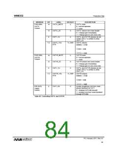
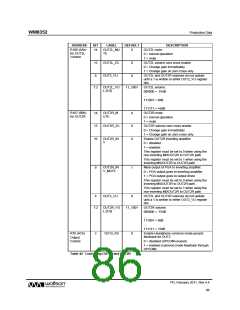
The control register fields for the OUT2L and OUT2R outputs are described in Table 42. The
available output configurations are shown in Section 13.9.3.
OUT2L_MUTE
R106 [14]
From left
output mixer
OUT2L
-1
OUT2L_VOL
R106 [7:2]
OUT2R_MUTE
R107 [14]
From right
output mixer
OUT2R
HPCOM
-1
OUT2R_VOL
R107 [7:2]
Vmid
OUT2_FB
R76 [2]
Figure 45 Headphone Outputs OUT2L and OUT2R
PD, February 2011, Rev 4.4
85
w

 WOLFSON [ WOLFSON MICROELECTRONICS PLC ]