Production Data
WM8352
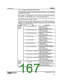
19.2 INITIATING AUXADC MEASUREMENTS
The AUXADC can measure voltages on four external pins, AUX1, AUX2, AUX3 and AUX4. It can
also measure voltages on the USB, LINE and BATT pins, and also the temperature sensor level.
Each of these 8 inputs can be independently selected or deselected as an AUXADC input. Whenever
the AUXADC is triggered, the AUXADC performs a measurement of each of the selected AUXADC
inputs. By default, none of the AUXADC inputs is selected. Therefore, the required inputs must be
enabled using the AUXADC_SELn bits prior to initiating an AUXADC measurement.
AUXADC measurements can be scheduled in a number of different ways, as determined by the
AUXADC_CTC register bit. In Polling Mode, a set of measurements is initiated by writing a logic ‘1’ to
the AUXADC_POLL bit. (This bit is then automatically reset once the measurements have been
completed.) In Continuous Mode, the WM8352 initiates a set of measurements at a time interval that
is determined by the AUXADC_CRATE field.
Additional control can be provided using a GPIO pin configured as a ‘MASK’ input (see Section 20).
The behaviour of the MASK input is selected using the AUXADC_MASKMODE register field - it can
be used to inhibit any measurements triggered by the Polling or Continuous modes, or else it can be
used as a hardware input to initiate a set of measurements.
Note that, when AUXADC_MASKMODE
= 11, then AUXADC_CTC, AUXADC_POLL and
AUXADC_CRATE have no effect. The polarity of the MASK input can be adjusted to be active high
or active low using the GPn_CFG bits defined in Section 20, where ‘n’ identifies the particular GPIO
pin in use.
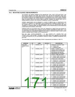
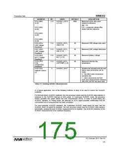
The control fields associated with initiating AUXADC measurements are defined in Table 115.
ADDRESS
R144 (90h)
Digitiser Control
(1)
BIT
LABEL
DEFAULT
DESCRIPTION
Continuous conversion mode:
0 = Polling mode
14
AUXADC_CTC
0
1 = Continuous mode
13
AUXADC_POLL
0
Writing “1” initiates a set of
measurements in polling mode
(AUXADC_CTC=0). This bit is
automatically reset after the
measurements are completed.
7
6
5
4
3
2
1
0
AUXADC_SEL8
AUXADC_SEL7
AUXADC_SEL6
AUXADC_SEL5
AUXADC_SEL4
AUXADC_SEL3
AUXADC_SEL2
AUXADC_SEL1
0
0
0
0
0
0
0
0
AUXADC TEMP input select
0 = Disable TEMP measurement
1 = Enable TEMP measurement
AUXADC BATT input select
0 = Disable BATT measurement
1 = Enable BATT measurement
AUXADC LINE input select
0 = Disable LINE measurement
1 = Enable LINE measurement
AUXADC USB input select
0 = Disable USB measurement
1 = Enable USB measurement
AUXADC AUX4 input select
0 = Disable AUX4 measurement
1 = Enable AUX4 measurement
AUXADC AUX3 input select
0 = Disable AUX3 measurement
1 = Enable AUX3 measurement
AUXADC AUX2 input select
0 = Disable AUX2 measurement
1 = Enable AUX2 measurement
AUXADC AUX1 input select
0 = Disable AUX1 measurement
1 = Enable AUX1 measurement
PD, February 2011, Rev 4.4
171
w

 WOLFSON [ WOLFSON MICROELECTRONICS PLC ]