W9412G6JH
9. ELECTRICAL CHARACTERISTICS
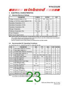
9.1 Absolute Maximum Ratings
PARAMETER
Voltage on any pin relative to VSS
Voltage on VDD/VDDQ supply relative to VSS
Operating Temperature (-4/-5)
Operating Temperature (-5I/-6I)
Operating Temperature (-5K)
Storage Temperature
SYMBOL
VIN, VOUT
VDD, VDDQ
TOPR
RATING
UNIT
V
-0.5 ~ VDDQ + 0.5
-1 ~ 3.6
0 ~ 70
V
°C
°C
°C
°C
°C
W
TOPR
-40 ~ 85
-40 ~ 105
-55 ~ 150
260
TOPR
TSTG
Soldering Temperature (10s)
Power Dissipation
TSOLDER
PD
1
Short Circuit Output Current
IOUT
50
mA
Note: Stresses greater than those listed under “Absolute Maximum Ratings” may cause permanent damage to the device.
This is a stress rating only, and functional operation of the device at these or any other conditions above those indicated in
the operational sections of this specification is not implied.
Exposure to absolute maximum rating conditions for extended periods may affect reliability.
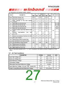
9.2 Recommended DC Operating Conditions
(TA = 0 to 70°C for -4/-5, TA = -40 to 85°C for -5I/-6I, TA = -40 to 105°C for -5K)
SYM.
VDD
PARAMETER
MIN.
2.3
TYP.
MAX.
2.7
UNIT NOTES
Power Supply Voltage (for -5/-5I/-5K/-6I)
Power Supply Voltage (for -4)
2.5
-
V
V
V
V
2
2
2
2
VDD
2.4
2.7
VDDQ
VDDQ
I/O Buffer Supply Voltage (for -5/-5I/-5K/-6I)
2.3
2.5
-
2.7
2.4
2.7
I/O Buffer Supply Voltage (for -4)
Input reference Voltage
VREF
VTT
0.49 x VDDQ 0.50 x VDDQ 0.51 x VDDQ
V
V
V
V
V
2, 3
2, 8
2
Termination Voltage (System)
Input High Voltage (DC)
VREF - 0.04
VREF + 0.15
-0.3
VREF
VREF + 0.04
VDDQ + 0.3
VREF - 0.15
VDDQ + 0.3
VIH (DC)
VIL (DC)
VICK (DC)
-
-
-
Input Low Voltage (DC)
2
Differential Clock DC Input Voltage
Input Differential Voltage.
CLK and CLK inputs (DC)
-0.3
15
VID (DC)
0.36
-
VDDQ + 0.6
V
13, 15
VIH (AC)
VIL (AC)
Input High Voltage (AC)
Input Low Voltage (AC)
Input Differential Voltage.
CLK and CLK inputs (AC)
VREF + 0.31
-
-
-
-
V
V
2
2
VREF - 0.31
VID (AC)
0.7
-
VDDQ + 0.6
V
13, 15
VX (AC)
Differential AC input Cross Point Voltage
Differential Clock AC Middle Point
VDDQ/2 - 0.2
VDDQ/2 - 0.2
-
-
VDDQ/2 + 0.2
VDDQ/2 + 0.2
V
V
12, 15
14, 15
VISO (AC)
Notes: VIH (DC) and VIL (DC) are levels to maintain the current logic state.
VIH (AC) and VIL (AC) are levels to change to the new logic state.
Publication Release Date: Nov. 29, 2011
Revision A03
- 23 -

 WINBOND [ WINBOND ]