Preliminary W91030B
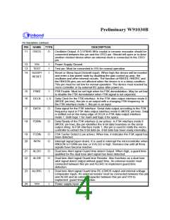
Pin Descriptions, continued
PIN
NAME TYPE
DESCRIPTION
11
OSCO
O
Oscillator Output. A 3.579545 MHz crystal or ceramic resonator should be
connected between this pin and the OSCI pin. Should left open or to drive
another clocked device when an external clock is connected to the OSCI
pin.
SS
12
13
14
V
I
I
I
Power Supply Ground.
SS
TEST
SLEEP/
RESET
Test pin. Must be connected to V for normal operation.
Reset or Sleep Input (Schmitt input). When high the device will be reseted
and enter a low power state by disabling the gain control op-amp, the
oscillator and other internal circuits. The function of RNGDI, RNGRC and
the RNGON pins are not affected when the device is in a sleep condition.
This pin must be set low for normal operation. The device must reseted by
micro controller or by external RC pulse after power on.
15
16
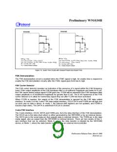
FSKE
DCLK
I
FSK Enable. Must be set high when for FSK demodulation. May be set low
to disable the FSK demodulator when FSK signal is not expected.
I, O Data Clock for the FSK interface. In the FSK data output interface mode 0
(MODE pin low), this pin is an output with a changing FSK frequency. In
the FSK interface mode 1, this pin is an input.
17
18
DATA
FDRN
O
Data signal for the FSK interface. Serial data output according to the FSK
frequency input in FSK data output interface mode 0 (MODE pin low). Data
is shifted out on the rising edge of DCLK in FSK data output interface
mode 1. Both logic 1 for mark and logic 0 for space.
O
Data Ready of the FSK interface (Low active). In FSK interface mode 0
(MODE pin low), this pin identifies the 8-bit data boundary on the serial
output string. In FSK interface mode 1, this pin is used to notify the micro-
controller to extract the 8-bit data (ie. 8-bit data has been ready internally).
19
20
FCDN
INTN
O
O
FSK Carrier Detect (Low active). When low, it indicates the FSK signal has
been detected.
Interrupt signal (open drain). It is used to interrupt the microcontroller when
RNGON or FDRN are low, or if ALGO is high. Remains low until all three
signals have become inactive.
21
22
ALGO
ALGR
O
O
Dual tone Alert signal Guard time detect Output. When high, a guard time
qualified for the dual tone alert signal has been detected.
Dual tone Alert signal Guard time Resistor. Also functions as a dual tone
alert signal detect output without guard time. An external resistor must
connected between this pin and ALGRC to implement guard time
detection.
23
24
ALGRC
I
I
Dual tone Alert signal Guard time RC (CMOS output and internal voltage
comparator input). An external resistor must be connected between this pin
and ALGR and an external capacitor between this pin and V to
DD
implement guard time detection.
DD
V
Power supply input.
- 4 -

 WINBOND [ WINBOND ]