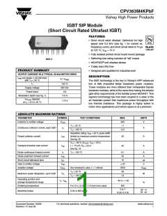
CPV363M4KPbF
IGBT SIP Module
(Short Circuit Rated
Ultrafast IGBT)
Vishay High Power Products
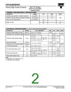
THERMAL AND MECHANICAL SPECIFICATIONS
PARAMETER
SYMBOL
TYP.
-
MAX.
UNITS
Junction to case, each IGBT, one IGBT in conduction
Junction to case, each DIODE, one DIODE in conduction
Case to sink, flat, greased surface
RthJC (IGBT)
3.5
RthJC (DIODE)
RthCS (MODULE)
-
5.5
°C/W
0.10
20
-
-
-
g
Weight of module
0.7
oz.
ELECTRICAL SPECIFICATIONS (TJ = 25 °C unless otherwise specified)
PARAMETER
SYMBOL
TEST CONDITIONS
MIN.
TYP.
-
MAX.
UNITS
V
(1)
Collector to emitter breakdown voltage
V(BR)CES
VGE = 0 V, IC = 250 µA
600
-
-
Temperature coeff. of breakdown voltage ΔV(BR)CES/ΔTJ
VGE = 0 V, IC = 1.0 mA
IC = 6.0 A
-
-
0.45
1.72
2.00
V/°C
2.10
VGE = 15 V
See fig. 2, 5
IC = 11 A
-
-
-
-
Collector to emitter saturation voltage
VCE(on)
V
IC = 6.0 A, TJ = 150 °C
VCE = VGE, IC = 250 µA
1.60
Gate threshold voltage
VGE(th)
3.0
-
-
6.0
Temperature coeff. of threshold voltage
Forward transconductance
ΔVGE(th)/ΔTJ
- 13
-
-
mV/°C
S
(2)
gfe
VCE = 100 V, IC = 12 A
VGE = 0 V, VCE = 600 V
3.0
-
6.0
-
250
Zero gate voltage collector current
ICES
µA
V
GE = 0 V, VCE = 600 V, TJ = 150 °C
-
-
-
-
-
2500
1.7
IC = 12 A
C = 12 A, TJ = 150 °C
VGE 20 V
1.4
1.3
-
Diode forward voltage drop
VFM
IGES
See fig. 13
V
I
1.6
Gate to emitter leakage current
=
100
nA
Notes
(1)
(2)
Pulse width ≤ 80 µs, duty factor ≤ 0.1 %
Pulse width 5.0 µs; single shot
www.vishay.com
2
For technical questions, contact: ind-modules@vishay.com
Document Number: 94485
Revision: 01-Sep-08

 VISHAY [ VISHAY ]