10-FU094PB017ME02-L620F36
datasheet
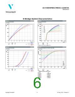
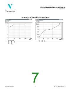
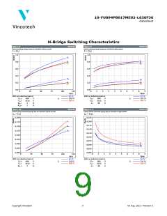
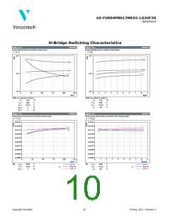
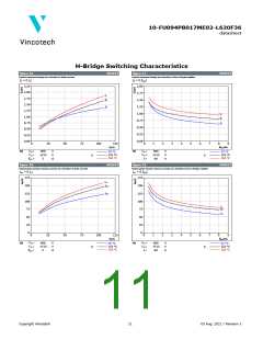
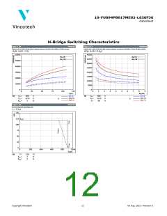
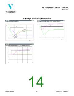
H-Bridge Switching Characteristics
figure 12.
MOSFET
figure 13.
MOSFET
Typical switching times as a function of drain current
Typical switching times as a function of gate resistor
t = f(ID)
t = f(Rg)
-1
10
-1
10
td(off)
td(off)
td(on)
tf
td(on)
-2
10
-2
10
tr
tf
tr
-3
10
-3
10
0
25
50
75
100
125
ID(A)
0
1
2
3
4
5
6
7
8
9
Rg(Ω)
With an inductive load at
With an inductive load at
Tj =
Tj =
150
600
-5/15
2
°C
V
150
600
-5/15
60
°C
V
VDS
=
=
=
=
VDS
=
=
=
VGS
Rgon
Rgoff
VGS
ID
V
V
Ω
Ω
A
2
figure 14.
MOSFET
figure 15.
MOSFET
Typical reverse recovery time as a function of drain current
Typical reverse recovery time as a function of turn off gate resistor
trr = f(ID)
trr = f(Rgoff)
0,0225
0,0200
0,0175
0,0150
0,0125
0,0100
0,0075
0,0050
0,0025
0,0000
0,0225
0,0200
0,0175
0,0150
0,0125
0,0100
0,0075
0,0050
0,0025
0,0000
trr
trr
trr
trr
trr
trr
0
25
50
75
100
125
ID(A)
0
1
2
3
4
5
6
7
8
9
Rgoff(Ω)
VDS
VGS
=
=
=
VDS
VGS
ID
=
=
=
At
600
-5/15
2
V
At
600
-5/15
60
V
25 °C
125 °C
150 °C
25 °C
125 °C
150 °C
V
V
A
Tj:
Tj:
Rgon
Ω
Copyright Vincotech
10
03 Aug. 2021 / Revision 1

 VINCOTECH [ VINCOTECH ]