TMC6200 DATASHEET (Rev. 1.01 / 2018-NOV-15)
21
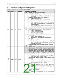
5.1 General Configuration Registers
GENERAL CONFIGURATION REGISTERS (0X00…0X0F)
R/W
Addr
n
Register
Description / bit names
Bit GCONF – Global configuration flags
disable: Driver Disable
1: Disable driver (e.g. for Resetting of short
condition)
singleline: Interface mode (reset default = 1)
0
1
2
0:
1:
Individual signals L+H
H-Input is control signal, L-Input is Enable
faultdirect
0:
Fault output active when at least one bridge is
shut down continuously due to overcurrent or
overtemperature
1:
Fault output shows each protective action of the
overcurrent shutdown
3 unused
5:4 amplification: Amplification of current amplifiers
RW
0x00
17
GCONF
0:
1:
2:
3:
Current amplification: *5
Current amplification: *10
(Current amplification: *10)
Current amplification: *20
6
7
amplifier_off:
0:
1:
Current sense amplifiers on
Amplifiers off (reduce power consumption)
test_mode
0:
Normal operation
1:
Enable analog test output on pin DRV_EN.
BBM_CLKS[1..0] selects the function of DRV_EN:
0…2: T120, DAC, VDDH
Attention: Not for user, set to 0 for normal operation!
31:8 unused
Bit GSTAT – Global status flags
(Re-Write with ‘1’ bit to clear respective flags, or cycle
DRV_EN to clear all bits except for reset and drv_otpw)
Attention: Switch off the affected MOSFET by its HS/LS
input in order to clear a pending short condition. Just
resetting the flag will not switch it on again.
reset
0
1
2
1:
Indicates that the IC has been reset. All registers
have been cleared to reset values.
Attention: DRV_EN must be high to allow clearing reset
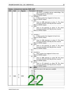
drv_otpw
R+
WC
0x01
15 GSTAT
1:
Indicates, that the driver temperature has
exceeded overtemperature prewarning-level. No
action is taken. This flag is latched.
drv_ot
1: Indicates, that the driver has been shut down
due to overtemperature. This flag can only be
cleared when the temperature is below the limit
again. It is latched for information.
ORed to STATUS output.
3
uv_cp
1:
Indicates an undervoltage on the charge pump.
www.trinamic.com

 TRINAMIC [ TRINAMIC MOTION CONTROL GMBH & CO. KG. ]