TMC6200 DATASHEET (Rev. 1.01 / 2018-NOV-15)
14
3.4 Tuning the MOSFET Bridge
A clean switching event is favorable to ensure low power dissipation and good EMC behavior.
Unsuitable layout or components endanger stable operation of the circuit. Therefore, it is important to
understand the effect of parasitic trace inductivity and MOSFET reverse recovery.
Stray inductance in power routing will cause ringing whenever the opposite MOSFET is in diode
conduction prior to switching on a low-side or high-side MOSFET. Diode conduction occurs during
break-before make time whenever the load current is inverse to the following bridge polarity. The
MOSFET bulk diode has a certain, type specific reverse recovery time and charge. This time typically is
in the range of a few 10ns. During reverse recovery time, the bulk diode will cause high current flow
across the bridge. This current is taken from the power supply filter capacitors (see thick lines Figure
3.5). Once the diode opens, parasitic inductance tries to keep the current flowing. A high, fast slope
results and leads to ringing in all parasitic inductivities (see Figure 3.6). This may lead to bridge
voltage undershooting the GND level as well as fast pulses on VS and all MOSFET connections. It
must be ensured, that the driver IC does not see spikes on its BM pins to GND going below -5V.
Severe VS ripple might overload the charge-pump circuitry. Measure the voltage directly at the driver
pins to driver GND. The amount of undershooting depends on energy stored in parasitic inductivities
from low side drain to low side source and via the sense resistor RS to GND.
When using relatively small MOSFETs, a soft slope control requires a high gate series resistance. This
endangers safe MOSFET switch off. Add additional diodes to ensure safe MOSFET off conditions with
slow switch-on slopes (Figure 3.9).
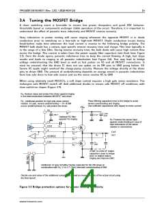
RG: Reduce slope and protect the driver against ringing
in the interconnections between MOSFET and driver
Place filtering capacitors near to the bridge to avoid
severe overshooting and ringing.
Use sufficient capacitance with regard to motor current.
RG ꢀꢁAdditional position for high side slope control
resistor. In case, severe undershooting < -5V of BM
occurs at BM terminal, RGꢂꢁwill protect the driver.
+VM
VS
1R
LOW-
ESR
220nF
4.7µF
Optional RC filter
against VS ringing
RP: Protects the sense input
against undershooting in case of
high inductance of the sense
resistor or connections
CV
HSV
V
CB
HS
LS
RG
Coil
out
RG
RS
VSENSE
LSV
RP
RG
1n,
100V
470pF to a few nF output
capacitors close to bridge
and / or output reduce
ringing and improve EMC
Additional 1A type Schottky Diodes (selected for full VM range) in
combination with RGꢂꢁꢃꢄꢁto 4.7 Ohm) eliminate undershooting of BM.
Decide use and value of the additional components based on measurements of the actual circuit using
the final layout!
Figure 3.5 Bridge protection options for power routing inductivity
www.trinamic.com

 TRINAMIC [ TRINAMIC MOTION CONTROL GMBH & CO. KG. ]