TMC6200 DATASHEET (Rev. 1.01 / 2018-NOV-15)
13
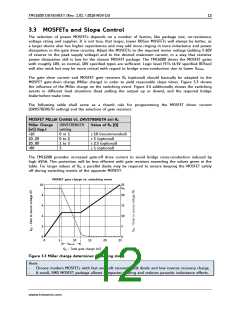
V12VOUT
Miller plateau
Lx
0V
VVM
Output
slope
Output
slope
BMx
0V
-1.2V
VVM+V12VOUT
VVM
Hx
0V
VCX-VBMx
Miller plateau
Hx-
BMx
0V
tBBM
tBBM
tBBM
Effective break-before-make time
Load pulling BMx down
Load pulling BMx up
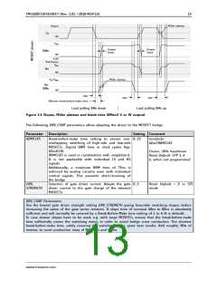
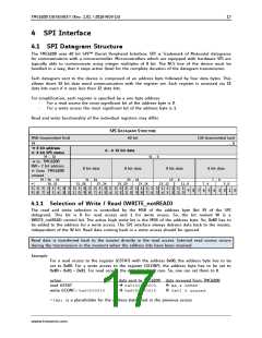
Figure 3.4 Slopes, Miller plateau and blank time (BMx=U V or W output)
The following DRV_CONF parameters allow adapting the driver to the MOSFET bridge:
Parameter
Description
Setting Comment
BBMCLKS
Break-before-make time setting to ensure non- 0…15
overlapping switching of high-side and low-side
MOSFETs. Digital BBM time in clock cycles (typ.
42ns/CLK).
BBMCLKS is used in combination with singleline=1.
It is not applicable with individual LS and HS
signals.
time[ns]
42ns*BBMCLKS
Ensure ~30% headroom
Reset Default: OTP 1..4
4, when not programmed
Additionally, a minimum BBM time of 75ns is
enforced by analog circuitry even with individual
control signals. This prevents short-circuiting of
the bridge
DRV_
STRENGTH
Selection of gate driver current. Adapts the gate 0…3
driver current to the gate charge of the external
MOSFETs.
Reset Default = 2 in SPI
mode
DRV_CONF Parameters
Use the lowest gate driver strength setting DRV_STRENGTH giving favorable switching slopes, before
increasing the value of the gate series resistors. A slope time of nominal 40ns to 80ns is absolutely
sufficient and will normally be covered by a Break-Before-Make time setting of 1 to 4 (4 is default).
In case slower slopes have to be used, e.g. with large MOSFETs, ensure that the break-before-make
time sufficiently covers the switching event, in order to avoid bridge cross conduction. The shortest
break-before-make time, safely covering the switching event, gives best results. Add roughly 30% of
reserve, to cover production stray of MOSFETs and driver.
www.trinamic.com

 TRINAMIC [ TRINAMIC MOTION CONTROL GMBH & CO. KG. ]