TMC4361 DATASHEET (Rev. 2.68 / 2015-Apr-14) Preliminary
14
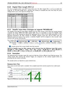
6.1.2 Digital Filter Length (FILT_L)
One bit is sampled within each (2SR)th input clock cycle. The filter length FILT_L can be set within the
range [0… 7]. The filter length FILT_L specifies the number of sampled bits that must have the same
voltage level to set a new input bit voltage level.
Configuration of digital filter length
FILT_L value
Filter length
No filtering
2 equal bits
3 equal bits
4 equal bits
5 equal bits
6 equal bits
7 equal bits
8 equal bits
0
1
2
3
4
5
6
7
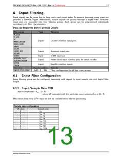
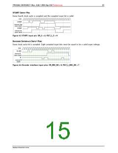
6.1.3 StepDir input filter (changes as regards TMC4361old)
The Step/Dir input filtering setup differs slightly from the other groups as the other four groups already
complete the whole INPUT_FILT_CONF register 0x03. Thus, it is possible to assign the Step/Dir input
group to one of the existing by setting the appropriate bit in front of the setup parameters. In the
following illustration, the filter settings for Step/Dir interface input pins will be taken from the
Reference input pin group. If no group is selected, Step/Dir will be assigned to the encoder input
interface filter group automatically.
31 30 29 28 27 26 25 24 23 22 21 20 19 18 17 16 15 14 13 12 11 10
9
8
7
6
5
4
3
2
1
0
Bits of register 0x03:
Input filter group:
Filter parameter:
Example:
Serial clock inputs
START input
Reference inputs
Encoder inputs
FILT_L_ENC_
SR_ENC_OUT
OUT
FILT_L_S
SR_S
FILT_L_REF
SR_ENC_REF
FILT_L_ENC_IN
SR_ENC_IN
0
0
0
0
0
0
0
0
0
1
0
0
0
0
1
0
1
0
1
1
0
1
1
0
0
1
1
0
0
1
0
1
= possible selection bits to assign Step/Dir input filter parameter
Figure 6.1 Step/Dir input pin filter settings will be derived from the Reference input filter group:
SR_SDIN = 6, FILT_L_SDIN = 3 (other input filter groups: SR_ENC_IN = 5, FILT_L_ENC_IN = 6,
SR_REF = 6, FILT_L_REF = 3, SR_S = 2, FILT_L_S = 4, SR_ENC_OUT = 0, FILT_L_ENC_OUT = 0)
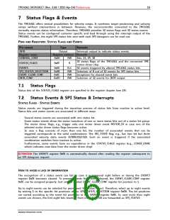
6.1.4 Examples
The following three examples depict the input pin filtering of three different input filtering groups. The
voltage levels after passing the Schmitt Trigger are compared to the internal signals which are
processed by the motion controller.
The sample points are depicted as green dashed lines.
REFERENCE INPUT PINS
Here, every second clock cycle is sampled. Two sampled input bits must be equal to be a valid input
voltage.
CLK
HOME
internal
home signal
STOPL
internal left
stop signal
Figure 6.2 Reference input pins: SR_REF = 1, FILT_L_REF = 1
www.trinamic.com

 TRINAMIC [ TRINAMIC MOTION CONTROL GMBH & CO. KG. ]