TMC248-LA DATASHEET (Rev. 1.01 / 2013-MAR-26)
9
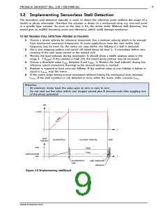
3.2 Implementing Sensorless Stall Detection
The sensorless stall detection typically is used, to detect the reference point without the usage of a
switch or photo interrupter. Therefore the actuator is driven to a mechanical stop, e.g. one end point
in a spindle type actuator. As soon as the stop is hit, the motor stalls. Without stall detection, this
would give an audible humming noise and vibrations, which could damage mechanics.
TO GET RELIABLE STALL DETECTION, PROCEED AS FOLLOWS:
1. Choose a motor velocity for reference movement. Use a medium velocity which is far enough
from mechanical resonance frequencies. In some applications even the start and/or stop
frequency may be used. So, the motor can stop within one fullstep if a stall is detected.
2. Use a sine stepping pattern and switch off mixed decay (at least 1… 3 microsteps before zero
crossing of the sine wave current in the related coil).
3. Monitor the load indicator during movement. It should show a stable readout value in the
range 3… 7 (LMOVE). If the readout is high (>5), the mixed decay portion may be increased.
4. Choose a threshold value LSTALL between 0 and LMOVE - 1. Monitor the load indicator during the
reference search movement (homing) as the desired velocity is reached.
5. Readout is required at least once per fullstep. If the readout value at one fullstep is below or
equal to LSTALL, stop the motor.
6. If the motor stops during normal movement without hitting the mechanical stop, decrease
LSTALL. If the stall condition is not detected at once, when the motor stalls, increase LSTALL
.
Attention:
-
-
At maximum motor load, the value goes to zero or near to zero.
Do not read out the value within one chopper period plus 8 microseconds after toggling one
of the phase polarities!
v(t)
v_max
x
a
m
_
a
t
load
indicator
acceleration
constant velocity
stall
max
LMOVE
LSTALL
stall threshold
min
t
acceleration
jerk
stall detected!
vibration
Figure 3.2 Implementing stallGuard
www.trinamic.com

 TRINAMIC [ TRINAMIC MOTION CONTROL GMBH & CO. KG. ]