TMC248-LA DATASHEET (Rev. 1.01 / 2013-MAR-26)
5
1.1 Advanced Features
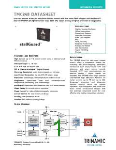
stallGuard™
The TMC248 offers sensorless load measurement and stall detection.
Its ability to predict an overload makes the TMC248 an optimum
choice for drives, where a high reliability is desired.
Further, the integrated stallGuard™ feature makes the TMC248 a
good choice for applications, where a reference point is needed,
but where a switch is not desired.
Current Control
Current control serves a cool driver and motor. Internal DACs allow
microstepping as well as smart current control. Its low power
dissipation makes the TMC248 an optimum choice for drives, where
a high reliability is desired.
Microstepping via SPI
Easy to use digital control of microstepping. After choosing the
desired microstep resolution the microcontroller sends digital
values for each microstep current via SPI. DACs and comparators
convert these digital values to analog signals for coil currents. This
way, every microstep is initialized and controlled by the
microcontroller. The TMC248 serves for the execution.
Mixed Decay
Mixed decay can be used for smoother operation.
Low Noise Chopper
The TMC248 allows implementing a low noise voltage PWM
chopper by two microcontroller PWM outputs using its simple
standalone mode. This way, a motor can be moved very smoothly
at high microstep resolution without any noise.
Slope Control
Slope control reduces electromagnetic emissions.
Oscillator and Clock Selector
Oscillator and clock selector provide the system clock from the on-
chip oscillator or an external source.
1.2 Control Interfaces
There are two control interfaces from the motion controller to the motor driver: the SPI serial
interface and the classical analog interface.
1.2.1 SPI Interface
The SPI interface is used to write control information to the chip and read back status information.
This interface must be used to initialize parameters and modes necessary to enable driving the motor.
This interface may also be used for directly setting the currents flowing through the motor coils. The
motor can be controlled through the SPI interface alone.
The SPI interface is a bit-serial interface synchronous to a bus clock. For every bit sent from the bus
master to the bus slave, another bit is sent simultaneously from the slave to the master.
Communication between an SPI master and the TMC248 slave always consists of sending one 12-bit
command word and receiving one 12-bit status word.
The SPI command rate typically corresponds to the microstep rate at low velocities. At high velocities,
the rate may be limited by CPU bandwidth to 10,000 to 100,000 commands per second, so the
application may need to change to fullstep resolution.
1.2.2 Classical Non-SPI Control Mode (Standalone Mode)
The driver can be controlled by analog current control signals and digital phase signals.
www.trinamic.com

 TRINAMIC [ TRINAMIC MOTION CONTROL GMBH & CO. KG. ]